
Cap screwing device

A hijab and mounting block technology, which is applied in the field of machinery, can solve the problems of poor practicality and complicated operation, and achieve the effects of convenient adjustment and operation, wide application range and reasonable structural design

Inactive Publication Date: 2017-11-17
江苏首达机械有限公司
View PDF7 Cites 0 Cited by
  • Summary
  • Abstract
  • Description
  • Claims
  • Application Information

AI Technical Summary

Problems solved by technology

[0003] The purpose of the present invention is to provide a cap screwing device to solve the problems of complicated operation and poor practicability in the prior art

Method used


Image

  • Cap screwing device

Examples


Embodiment Construction

[0018] In order to make the purpose, technical solutions and advantages of the embodiments of the present invention clearer, the technical solutions in the embodiments of the present invention will be clearly and completely described below in conjunction with the drawings in the embodiments of the present invention. Obviously, the described embodiments It is a part of embodiments of the present invention, but not all embodiments.

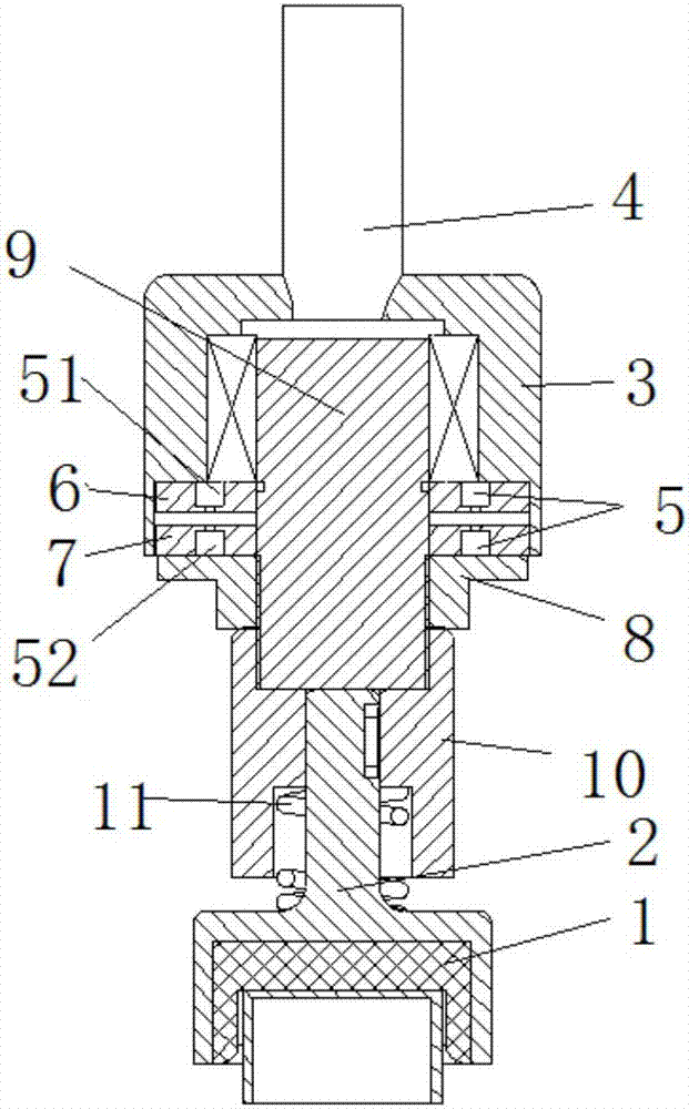
[0019] Such as figure 1 As shown, the embodiment of the present invention provides a capping device, including a capping head 1, a capping column 2, a housing 3 and a rotating shaft 4 for connecting an external drive device, and the capping head 1 is installed at the bottom of the capping column 2 end, the housing 3 is connected to the rotating shaft 4, and also includes a set of permanent magnets 5 with N poles 51 and S poles 52 separately arranged. In the groove of the installation block two 7, there is a gap between the N pole 51 and the S pole ...


PUM


Abstract

The invention relates to a cap screwing device. The cap screwing device comprises a cap screwing head, a cap screwing post, a shell and a rotary shaft used for being connected with an external driving device. The cap screwing head is mounted at the lower end of the cap screwing post. The shell is connected with the rotary shaft. The cap screwing device further comprises a set of permanent magnets with N poles and S poles separated. The N poles and the S poles of the permanent magnets are arranged in grooves of a mounting block I and a mounting block II. Gaps are reserved between the N poles and the S poles of the permanent magnets. The mounting block I is connected with the shell through a fastener. The mounting block II is connected with an adjusting seat. The adjusting seat is connected with a center shaft. The center shaft is sleeved with the mounting block I, the mounting block II and the adjusting seat. The bottom of the center shaft is connected with the cap screwing post. The cap screwing device is reasonable in structure design, capable of realizing automatic cap screwing, simple in structure, convenient to adjust and operate and capable of conducting batched adjustment.

Description

technical field [0001] The invention relates to the field of machinery, and specifically designs a cap screwing device. Background technique [0002] Filling is more and more widely used in food packaging. It is a very important step in the process of filling food packaging to tighten the sealing cap and seal the material in the bottle. Therefore, a set of convenient, quick and easy-to-operate capping mechanism is a key problem that must be solved in filling and packaging. The existing capping device usually adopts the form of spring shrapnel to fix the torque. During mass production, the manufacturing requirements for the shrapnel and the spring are relatively high. Two mechanisms manufactured in the same batch have a large difference in torque, long debugging time, complicated operation, and poor practicability. . Contents of the invention [0003] The object of the present invention is to provide a cap screwing device to solve the problems of complicated operation and...

Claims


Application Information

Patent Timeline
Patent Type & Authority Applications(China)
IPC IPC(8): B67B3/20
CPCB67B3/20
Inventor 丁振庭
Owner 江苏首达机械有限公司
Learn More