
Discharging device

A discharge device and discharge port technology, applied in the directions of packaging, transportation and packaging, loading/unloading, etc., can solve the problems of reducing production efficiency, operating hazards, effective outflow, etc., and achieve the effect of reducing overall costs and avoiding risks

Pending Publication Date: 2021-02-12
广州红尚机械制造有限公司
View PDF0 Cites 0 Cited by
  • Summary
  • Abstract
  • Description
  • Claims
  • Application Information

AI Technical Summary

Problems solved by technology

[0002] At present, in the chemical or food industry, after the slurry is prepared, the fluidity will be poor due to the high viscosity of the fluid, and it will not be able to flow out effectively by gravity. It is necessary to increase the press machine to assist the discharge by increasing the pressure.
Due to the addition of a press machine to the equipment, the manufacturing cost has been increased, and the press machine is a high-pressure device, so the operation has certain risks. In addition, the finished fluid needs to be transferred to the press machine for discharge by using the barrel, which reduces the production efficiency. , increasing the complexity of the operation

Method used


Image

  • Discharging device
  • Discharging device

Examples


Embodiment Construction

[0018] The idea, specific structure and technical effects of the present invention will be clearly and completely described below in conjunction with the embodiments and accompanying drawings, so as to fully understand the purpose, features and effects of the present invention. Apparently, the described embodiments are only some of the embodiments of the present invention, rather than all of them. Based on the embodiments of the present invention, other embodiments obtained by those skilled in the art without creative efforts belong to The protection scope of the present invention. In addition, all connection relationships mentioned in this article do not refer to the direct connection of components, but mean that a better connection structure can be formed by adding or reducing connection accessories according to specific implementation conditions. The various technical features in the invention can be combined interactively on the premise of not conflicting with each other. ...


PUM


Abstract

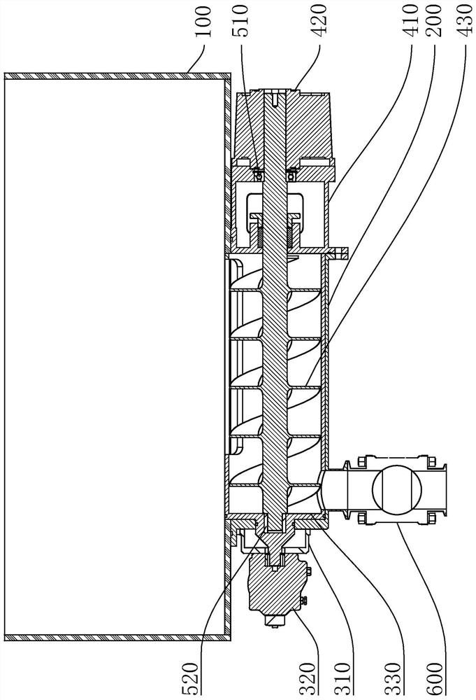
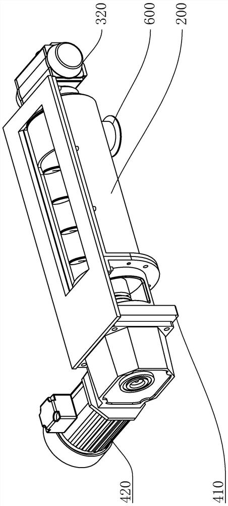
The invention discloses a discharging device which comprises a container of which the bottom side is provided with a discharging opening, a discharging pipe shell, a first rotary driving piece and a second rotary driving piece; the discharging pipe shell is arranged on the bottom side of the container, a pipe shell inlet is formed in the position, directly facing the discharging port, of the discharging pipe shell, and a pipe shell outlet is formed in the bottom side of the discharging pipe shell; the first rotary driving piece is connected to one end of the discharging pipe shell, a spacer bush is arranged in the discharging pipe shell, a feeding inlet and a feeding outlet are formed in the side wall of the spacer bush, the first rotary driving piece is connected to the spacer bush in a driving mode, and the first rotary driving piece can drive the spacer bush to rotate and enable the feeding inlet and the feeding outlet to directly face the pipe shell inlet and the pipe shell outletrespectively; and the second rotary driving piece is connected with the other end of the discharging pipe shell and is in driving joint with a conveying screw. According to the discharging device, a material pressing machine is omitted, the overall cost is reduced, risks caused by using the material pressing machine are avoided, and the discharging device is particularly suitable for discharging of high-viscosity materials.

Description

technical field [0001] The invention relates to a feeding device, in particular to a discharging device. Background technique [0002] At present, in the chemical or food industry, after the slurry is prepared, the fluidity will be poor due to the high viscosity of the fluid, and it will not be able to flow out effectively by gravity. It is necessary to increase the pressure to assist the discharge by increasing the pressure. Due to the addition of a press machine to the equipment, the manufacturing cost has been increased, and the press machine is a high-pressure device, so the operation has certain risks. In addition, the finished fluid needs to be transferred to the press machine for discharge by using the barrel, which reduces the production efficiency. , increasing the complexity of the operation. Contents of the invention [0003] The purpose of the present invention is to provide a discharge device to solve one or more technical problems in the prior art, and at le...

Claims


Application Information

Patent Timeline
Patent Type & Authority Applications(China)
IPC IPC(8): B65G65/46B65G33/24B65G33/26
CPCB65G33/24B65G33/265B65G65/46
Inventor 吕柏良李龙涛余胜杜健付奇郑宇
Owner 广州红尚机械制造有限公司
Learn More