Hanging tower for laboratory

A laboratory and pendant technology, applied in applications, household heating, household appliances, etc., can solve problems such as inconvenient walking, messy pipelines, etc., and achieve the effects of accurate action, improved practicability, and improved safety

Active Publication Date: 2021-02-12
郑州利生科教设备有限公司
View PDF9 Cites 1 Cited by
  • Summary
  • Abstract
  • Description
  • Claims
  • Application Information

AI Technical Summary

Problems solved by technology

[0003] The purpose of the present invention is to overcome the deficiencies in the prior art, to solve or at least alleviate the problems of inconvenient walking and messy suspended pipelines caused by the laying of pipelines in the laboratory on the ground, and to provide a pendant for the laboratory

Method used


Image

  • Hanging tower for laboratory
  • Hanging tower for laboratory
  • Hanging tower for laboratory

Examples


Embodiment 1

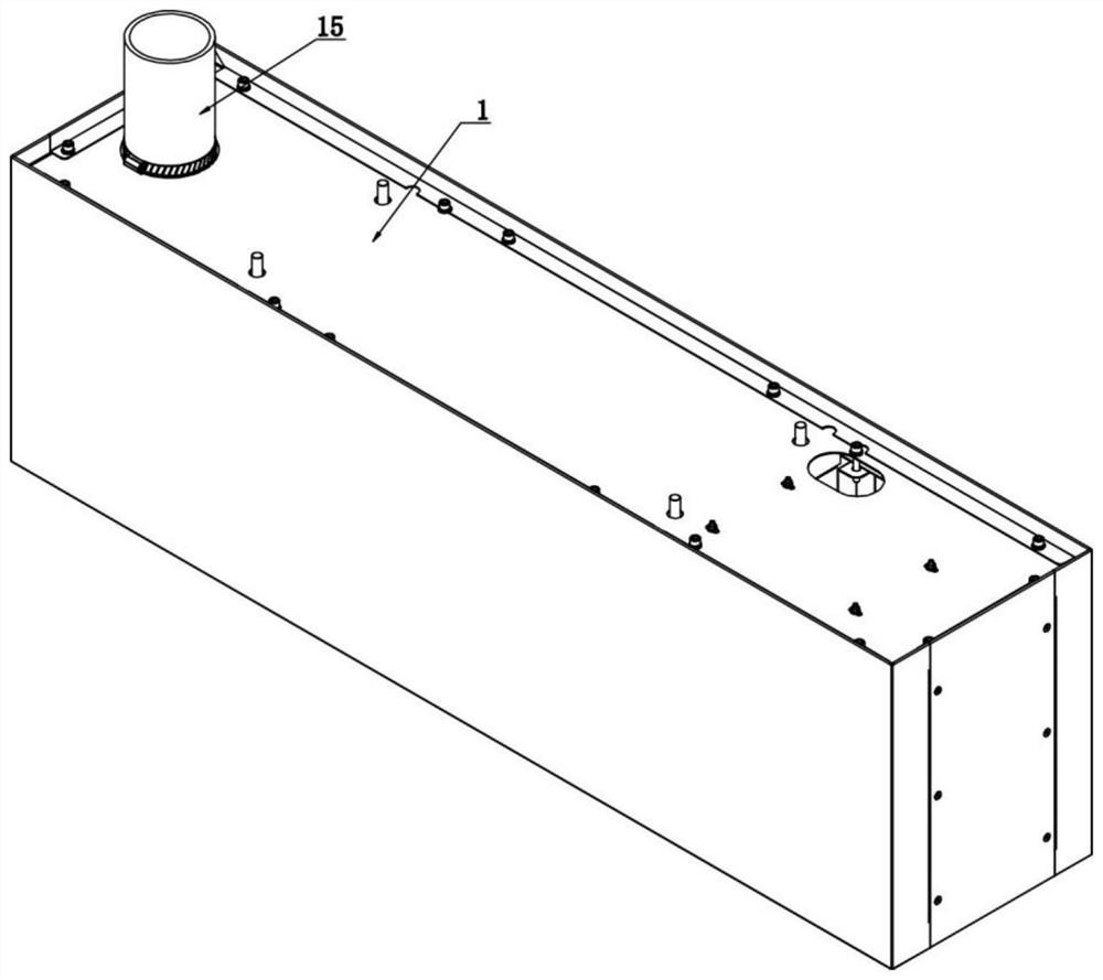
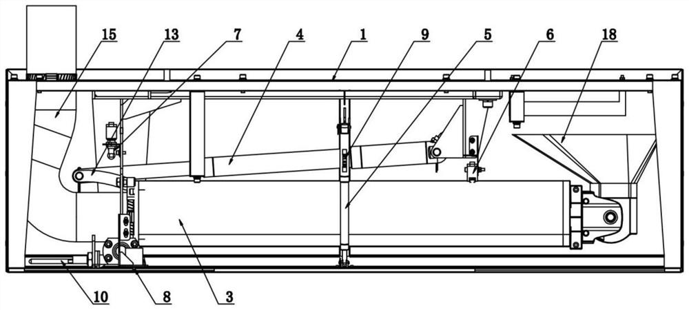
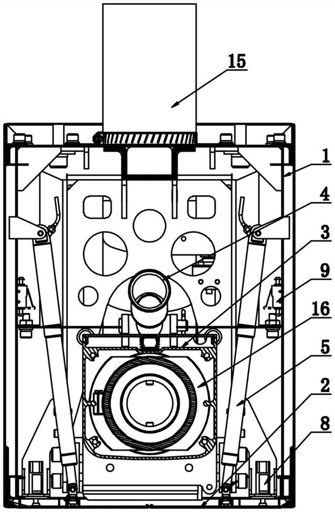
[0048] Such as Figure 1-11 As shown, a pendant tower for a laboratory is installed on the ceiling of the laboratory. The pendant tower includes an outer frame 1, an opening and closing door 2, a rotating arm 3, a first telescopic rod 4 and a second telescopic rod 5 , the outer frame 1 is a rectangular shell with an open lower end, the opening and closing door 2 and the second telescopic rod 5 are two mutually symmetrically arranged, the outer side of the opening and closing door 2 is hinged with the lower end of the side wall at the opening of the outer frame 1, and the two The inner sides of the opening and closing doors 2 overlap each other, one end of the second telescopic rod 5 is hinged to the inner side of the side wall of the outer frame 1, and the other end is hinged to the inner side of the opening and closing door 2, and the rotating arm 3 is horizontally installed in the outer frame 1. The lower part is rotatably connected with the outer frame 1, the first telescop...

Embodiment 2

[0063] Such as Figure 12-17 As shown, the similarities between embodiment 2 and embodiment 1 are no longer repeated, and the difference is:

[0064] The section of the partition 11 is T-shaped, and the circuit area 301 of the rotating arm 3 is provided with an LED light bar 14, which is fixedly arranged on the horizontal section of the partition 11, and the top surface of the rotating arm 3 is provided with a LED light bar 14 corresponds to a slot, and a light-transmitting plate made of a transparent material is arranged at the slot.

[0065] The rotating end of the rotating arm 3 is fixedly provided with a power socket 21 , and the power socket 21 is connected to the circuit pipe network through wires, and the wires are located in the circuit area 301 of the rotating arm 3 .

[0066] The rotating end of the pivoting arm 3 is provided with a water inlet connector 22 and a drain connector 23, the water inlet connector 22 is connected to the water inlet pipe network through th...

Embodiment 3

[0069] Such as Figure 18 As shown, the similarities between embodiment 3 and embodiment 1 are no longer repeated, and the difference is:

[0070] The upper part of the pendant tower is provided with a lifting device 28, the lower end of the lifting device 28 is fixedly connected with the upper surface of the pendant tower, and the upper end is fixedly arranged on the roof of the laboratory. When the rotating arm 3 is in the experimental state and its position is still high, the lifting device 28 Drive the pendant to descend as a whole, so that the rotating arm 3 is positioned at the normal use position.


PUM


Abstract

The invention relates to a hanging tower for a laboratory. The hanging tower is arranged at a suspended ceiling of the laboratory and comprises an outer frame, two opening and closing doors, a rotating arm, a first telescopic rod and two second telescopic rods, the outer frame is a rectangular shell with an opening in the lower end, both the two opening and closing doors and the two second telescopic rods are symmetrically arranged, and the outer sides of the opening and closing doors are hinged to the lower ends of the side walls of the opening of the outer frame; the inner sides of the two opening and closing doors are in lap joint, one ends of the second telescopic rods are hinged to the inner side of the side wall of the outer frame, the other ends of the second telescopic rods are hinged to the opening and closing doors, the rotating arm is transversely arranged in the outer frame, and the lower portion of the hinged end of the rotating arm is rotationally connected with the outerframe; and the first telescopic rod is located on the upper portion of the rotating arm, one end of the first telescopic rod is hinged to the upper portion of the hinged end of the rotating arm, andthe other end of the first telescopic rod extends to the rotating end of the rotating arm and is hinged to the outer frame. The hanging tower for the laboratory is provided for solving or at least relieving the problems of inconvenient walking and messy suspended pipelines caused by the fact that the pipelines are arranged on the ground in the laboratory.

Description

technical field [0001] The invention relates to the technical field of laboratory auxiliary equipment, in particular to a pendant tower used in a laboratory. Background technique [0002] In the laboratory, each test bench needs to provide circuit interfaces, water supply and drainage interfaces, etc. At present, most of the pipelines are laid on the ground, but the ground space is limited, and more pipelines will cause walking inconvenience. Therefore, some pipelines will be laid on the roof of the laboratory and hidden in the ceiling of the roof, but the distance between the ceiling and the test bench is far away. Clutter not only affects the appearance but also interferes with the experiment. Contents of the invention [0003] The purpose of the present invention is to overcome the deficiencies in the prior art, solve or at least alleviate the problems of inconvenient walking and messy suspended pipelines caused by pipelines laid on the ground in the laboratory, and pr...

Claims


Application Information

Patent Timeline
Patent Type & Authority Applications(China)
IPC IPC(8): E04B9/00E04B9/02F16L3/00F21V33/00F24F7/06F24F13/02
CPCE04B9/00E04B9/003E04B9/006E04B9/02F24F7/065F24F13/0227F21V33/006F16L3/00F21Y2115/10
Inventor 丁晓东楚文辉赵广涛
Owner 郑州利生科教设备有限公司
Why Eureka
Try Eureka