
Corrugated web H-shaped steel beam

A corrugated, corrugated web technology, applied in the direction of joists, girders, trusses, etc., can solve the problem of reducing the firmness of the connection between the steel beam and the concrete, the influence of the mechanical performance of the steel beam connection end, and the inability to reuse the lifting lugs, etc. problems, to achieve the effect of saving disassembly time, improving fastening safety and improving connection firmness

Pending Publication Date: 2021-02-12
SHAN DONG JUXIN GRP STEEL STRUCTURE CO LTD
View PDF0 Cites 0 Cited by
  • Summary
  • Abstract
  • Description
  • Claims
  • Application Information

AI Technical Summary

Problems solved by technology

[0003] At present, in order to ensure the support strength of the corrugated web H-shaped steel girder, most of the corrugated webs do not have rough hook grooves to increase the contact area with the concrete, thereby reducing the connection between the steel girder and the concrete. Firmness, and most of the lifting lugs set on the existing steel beams are fixed to the surface of the steel beams by welding. When disassembling, it takes more time to cut, and it may make the lifting lugs unable to be reused. When steel girders are installed with other main girders, most of them are welded, which not only makes the construction inconvenient, but also affects the mechanical properties of the steel girder joints to a certain extent.

Method used


Image

  • Corrugated web H-shaped steel beam
  • Corrugated web H-shaped steel beam
  • Corrugated web H-shaped steel beam

Examples


Embodiment Construction

[0032] The following will clearly and completely describe the technical solutions in the embodiments of the present invention with reference to the accompanying drawings in the embodiments of the present invention. Obviously, the described embodiments are only some, not all, embodiments of the present invention. Based on the embodiments of the present invention, all other embodiments obtained by persons of ordinary skill in the art without making creative efforts belong to the protection scope of the present invention.

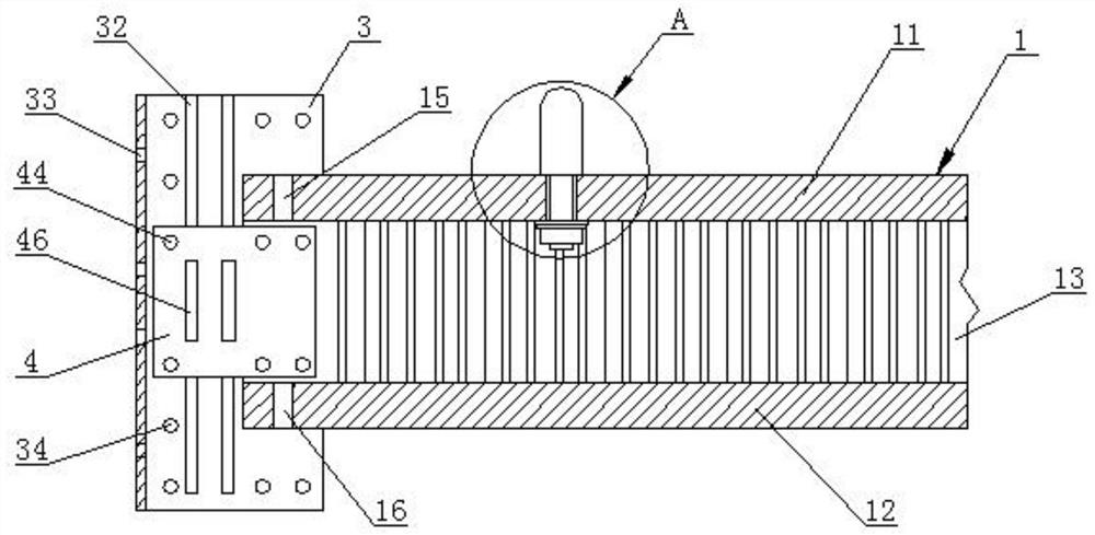
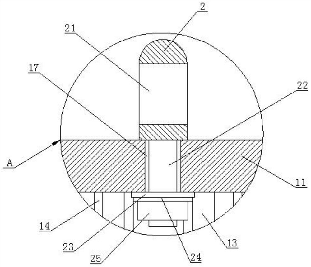
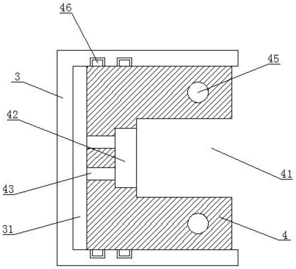
[0033] see Figure 1-3, a corrugated web H-shaped steel beam, including a steel beam 1, the steel beam 1 includes an upper flange 11, a lower flange 12, a corrugated web 13, a vertical groove 14, an upper positioning hole 15, a lower positioning hole 16 and The mounting holes 17, the upper flange 11 and the lower flange 12 are respectively fixedly connected to the upper and lower ends of the corrugated web 13, the vertical grooves 14 are equidistantly distribu...


PUM


Abstract

The invention discloses a corrugated web H-shaped steel beam, and belongs to the technical field of building construction tools. The corrugated web H-shaped steel beam comprises an upper wing plate, alower wing plate, a corrugated web, vertical grooves, an upper positioning hole, a lower positioning hole and mounting holes, wherein the upper wing plate and the lower wing plate are fixedly connected to the upper and lower ends of the corrugated web respectively, and the vertical grooves are distributed in two side surfaces of the corrugated web at equal intervals. According to the corrugated web H-shaped steel beam, the staggered vertical grooves are formed in both sides of the corrugated web, so that the friction strength of the side surfaces of the corrugated web can be increased in thecondition that the support strength of the corrugated web is not influenced, and when the steel beam and concrete are poured, the connection firmness is increased; a lifting lug is arranged and has splitting and combining functions, so that the disassembly time of the lifting lug is saved, and the lifting lug can be repeatedly used; and a positioning block and a connecting base are arranged, so that the steel beam and other main beams can be conveniently and rapidly positioned and connected, and the installation efficiency of the steel beam is greatly improved.

Description

technical field [0001] The invention relates to the technical field of building construction tools, and more specifically relates to a corrugated web H-shaped steel girder. Background technique [0002] The corrugated steel web steel girder is generally composed of steel top plate, steel bottom plate and corrugated steel web. Force, the overall structure formed in this way bears the load together. [0003] At present, in order to ensure the support strength of the corrugated web H-shaped steel beam, most of the corrugated webs do not have rough hook grooves to increase the contact area with the concrete, thereby reducing the connection between the steel beam and the concrete. Firmness, and most of the lifting lugs set on the existing steel beams are fixed to the surface of the steel beams by welding. When disassembling, it takes more time to cut, and it may make the lifting lugs unable to be reused. When steel girders are installed with other main girders, they are mostly ...

Claims


Application Information

Patent Timeline
Patent Type & Authority Applications(China)
IPC IPC(8): E04C3/06E04C3/07
CPCE04C3/06E04C3/07
Inventor 田利王传祥
Owner SHAN DONG JUXIN GRP STEEL STRUCTURE CO LTD
Learn More