
Vehicle-mounted laser radar temperature compensation system and method

A vehicle-mounted laser radar and temperature compensation technology, which is applied in radio wave measurement systems, electromagnetic wave re-radiation, and utilization of re-radiation, etc., can solve the problem of affecting the accuracy of facial recognition payment, facial unlocking scene recognition, and ranging accuracy. Problems such as large working temperature range, to achieve the effect of solving the brightness difference of the grayscale image, low dependence, and improving accuracy

Pending Publication Date: 2021-02-12
HANGZHOU GUANGPO INTELLIGENT TECH CO LTD
View PDF7 Cites 3 Cited by
  • Summary
  • Abstract
  • Description
  • Claims
  • Application Information

AI Technical Summary

Problems solved by technology

However, in the vehicle field, its operating temperature range is large, and most electronic components will enter the nonlinear region, which will lead to a sharp decline in ranging accuracy.
In addition, due to temperature changes, the positions of the laser signal and the shutter signal in the time domain also change, which will also cause drastic changes in the grayscale value of the grayscale image output by the lidar, which will be too dark or overexposed, which will affect the facial recognition payment. Or the recognition accuracy of unlocking the scene by swiping the face

Method used


Image

  • Vehicle-mounted laser radar temperature compensation system and method
  • Vehicle-mounted laser radar temperature compensation system and method
  • Vehicle-mounted laser radar temperature compensation system and method

Examples


Embodiment Construction

[0056] The present invention will be described in detail below in conjunction with the specific embodiments shown in the accompanying drawings, but these embodiments do not limit the present invention, those of ordinary skill in the art make structural, method, or functional changes based on these embodiments All are included in the scope of protection of the present invention.

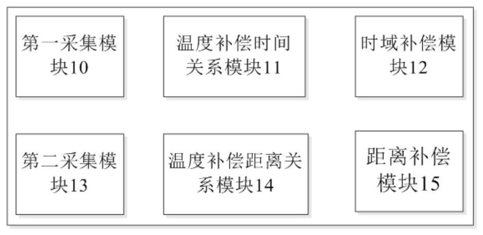
[0057] like figure 1 One embodiment of the present invention shown, the present invention provides a kind of vehicle lidar temperature compensation system, described system comprises:

[0058] The first collection module 10 is used to collect the distance measured by the lidar at different test temperatures to form the first set of data that the distance varies with temperature;

[0059] The temperature compensation time relationship module 11 is used to construct a distance temperature change curve relationship according to the first set of data, and generate a functional relationship between compen...


PUM


Abstract

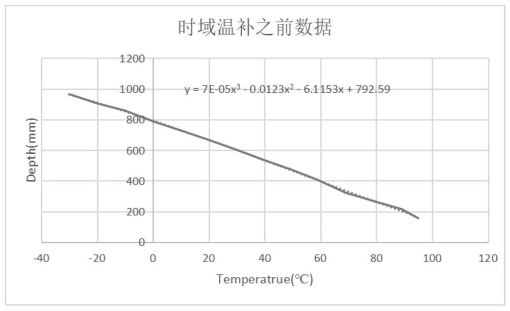
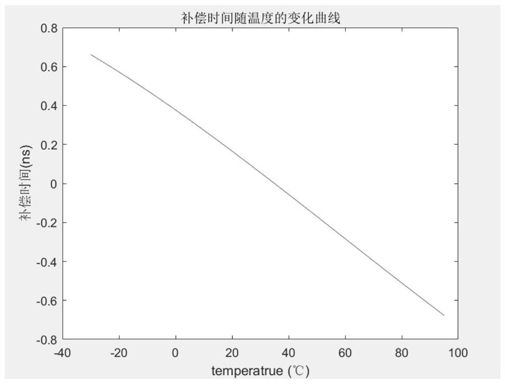
The invention discloses a vehicle-mounted laser radar temperature compensation system. The system collects distances measured by a laser radar at different test temperatures, constructs a distance andtemperature change curve relationship, generates a function relationship between compensation time and temperature, obtains the current temperature of the laser radar when the next frame of depth image of the laser radar is exposed, calculates the compensation time corresponding to the current temperature, increases the compensation time for a shutter signal of the laser radar, completes the timedomain compensation of the laser radar, corrects the brightness change of a grey-scale map caused by the change of the laser radar along with the temperature, collects the distances measured by the laser radar at all test temperatures on the basis of the time domain compensation, carries out cubic spline interpolation, generates a spline interpolation table of which the distance changes along with the temperature, and establishes a corresponding relation between the temperature and the compensation distance; the corresponding compensation distance is searched according to the current temperature of the laser radar, and the compensation distance is increased for the next frame of depth image, so that the linear region and the nonlinear region of an electronic device have high distance compensation precision.

Description

technical field [0001] The invention relates to the technical field of vehicle-mounted laser radar, in particular to a temperature compensation system and method for vehicle-mounted laser radar. Background technique [0002] As a representative of 3D vision equipment, lidar has been widely used in our lives, such as face payment, face unlocking, etc. In the field of vehicles, such as unmanned driving, literacy, face recognition, in-vehicle behavior recognition and other fields, lidar is also used more and more. LiDAR measures the distance by detecting the gray scale relationship between two adjacent groups of laser signals reflected back. The laser signal of the lidar and the shutter signal of the lidar are sensitive to temperature. As the temperature changes, the phase of the two will also change, resulting in ranging deviation. [0003] In the prior art, feedback adjustment is generally performed by increasing the temperature compensation coefficient. This solution is si...

Claims


Application Information

Patent Timeline
Patent Type & Authority Applications(China)
IPC IPC(8): G01S7/48G01S17/08
CPCG01S7/48G01S17/08
Inventor 王坤强应忠建杨金峰吴晟张合勇
Owner HANGZHOU GUANGPO INTELLIGENT TECH CO LTD
Learn More