Cover for operating element and operating assembly

A technology for operating elements and covering parts, which is applied to devices, control components, and instruments that prevent/restrict/restore the movement of parts of a control mechanism.

Inactive Publication Date: 2021-02-12
BCS AUTOMOTIVE INTERFACE SOLUTIONS GMBH
View PDF0 Cites 0 Cited by
  • Summary
  • Abstract
  • Description
  • Claims
  • Application Information

AI Technical Summary

Problems solved by technology

This is disadvantageous, however, because glass or other solid materials are rigid and thus complicate the tactile feedback when operating the operating components

Method used


Image

  • Cover for operating element and operating assembly
  • Cover for operating element and operating assembly
  • Cover for operating element and operating assembly

Examples


Embodiment Construction

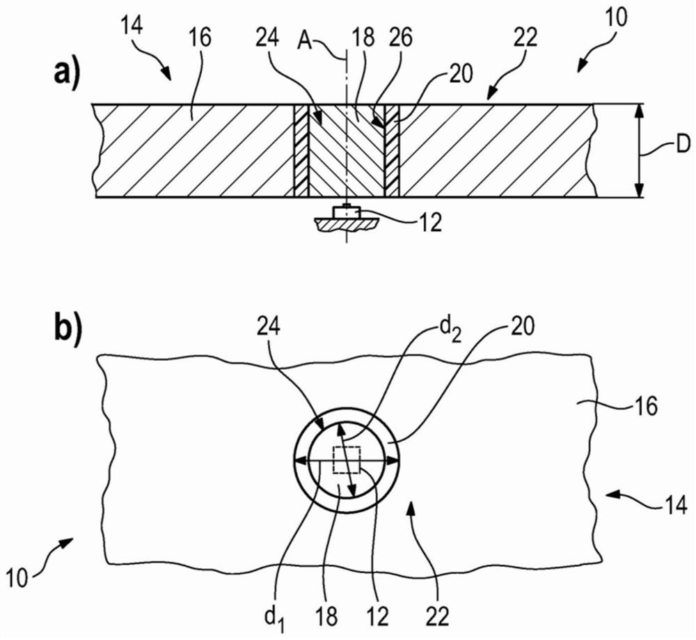
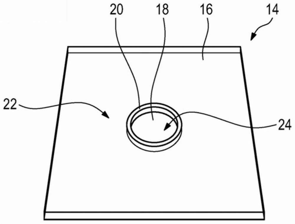
[0027] figure 1 a and 1 b show a sectional or side view of the operating assembly 10 with the operating element 12 and the cover 14 for the operating element 12 . exist figure 2 A perspective view of the operating unit 10 can be seen in .

[0028] FIG. 14 includes a basic body 16 , a button part 18 and a support ring 20 .

[0029] In the exemplary embodiment shown, the base body 16 is a plate made of a solid solid material, such as glass, which has two flat, parallel surfaces. Alternatively, the base body 16 can consist of transparent plastic.

[0030] Of course, the base body 16 and / or the button part 18 can also be produced from metal, ceramics, wood or other rigid solid materials.

[0031] The surface of the base body 16 facing the operator of the operating assembly 10 forms the operating surface 22 of the cover 14 .

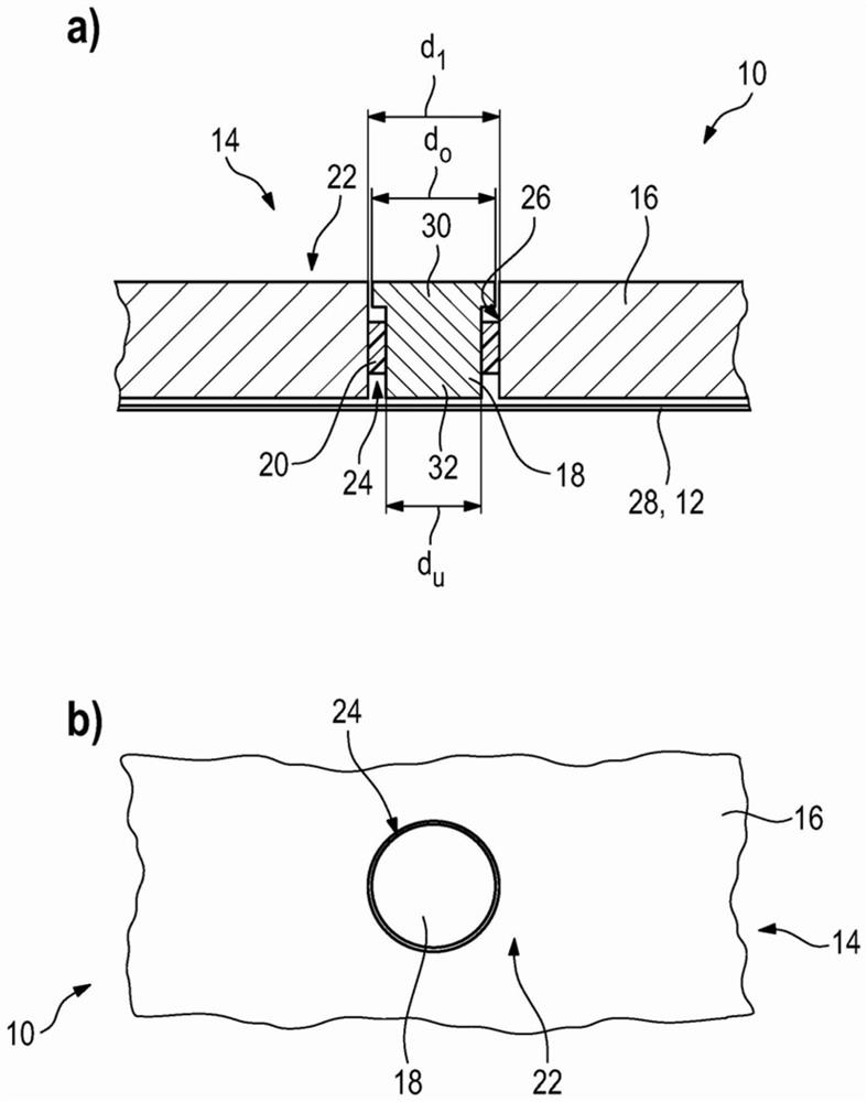
[0032] In the base body 16 , in particular perpendicularly to the operating surface 22 , a through-opening 24 is formed, which extends through the enti...


PUM


Abstract

The invention relates to a cover (14) for an operating element (12). The cover comprises a solid base body (16) having an operating surface (22); and at least one solid button element (18) for operating the operating element (12), wherein the base body (16) has at least one passage opening (24) which extends completely through the base body (16) starting from the operating surface (22). The push-button element (18) is fixed in a through-opening (24) on the base body (16) such that the push-button element (18) is movable in the axial direction (A) and is flush with the operating surface (22) inan non-operative state. Furthermore, an operating assembly (10) is shown.

Description

technical field [0001] The invention relates to a cover for an operating element and to an operating assembly having at least one operating element. Background technique [0002] The operating unit with operating elements must generally function flawlessly not only from a technical point of view, but also from an optical point of view. Operating components are usually also arranged above the display in order to realize a combined input-output device. [0003] For this reason, glass or other transparent solid materials are usually used as covers for the operating elements. This is disadvantageous, however, since glass or other solid materials are rigid and thus complicate the tactile feedback when operating the operating component. Contents of the invention [0004] It is therefore the object of the present invention to provide a cover for an operating element and an operating assembly in which a solid material is used as the cover, while at the same time enabling a tacti...

Claims


Application Information

Patent Timeline
IPC IPC(8): G05G1/02
CPCG05G1/02G05G5/03
Inventor 泽伦·莱姆克尼古拉·波米特金蒂莫·舒伯特
Owner BCS AUTOMOTIVE INTERFACE SOLUTIONS GMBH
Why Eureka
Try Eureka