
Transfer printing machine

A printing machine and printing technology, which is applied in the direction of rotary printing machine, printing machine, transfer printing, etc., can solve the problems of increased process, heavy coil material, high labor cost, etc., and achieve the effect of uniform distribution of cold water

Active Publication Date: 2021-02-19
绍兴柯桥兰嵋数码纺织科技有限公司
View PDF17 Cites 0 Cited by
  • Summary
  • Abstract
  • Description
  • Claims
  • Application Information

AI Technical Summary

Problems solved by technology

This has relatively large limitations. For example, for some fabrics that need to be pretreated, it will require rewinding after pretreatment before cutting, which will increase the process.
Moreover, due to the use of the coil material loading method, it is necessary to stop the machine to change the roll after the material on the coil material is used up, which will also cause a waste of time and cost. In addition, the coil material is usually relatively heavy, and many people are needed to complete the material loading. Therefore, at least two workers are usually required to look after and operate, and the labor cost is also high. Therefore, the production cost of the current transfer printing machine is relatively high

Method used


Image

  • Transfer printing machine
  • Transfer printing machine
  • Transfer printing machine

Examples


Embodiment 1

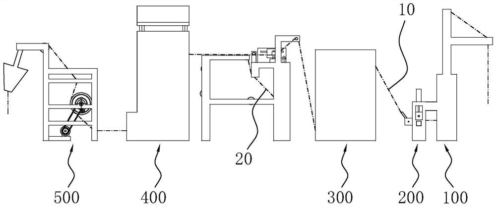
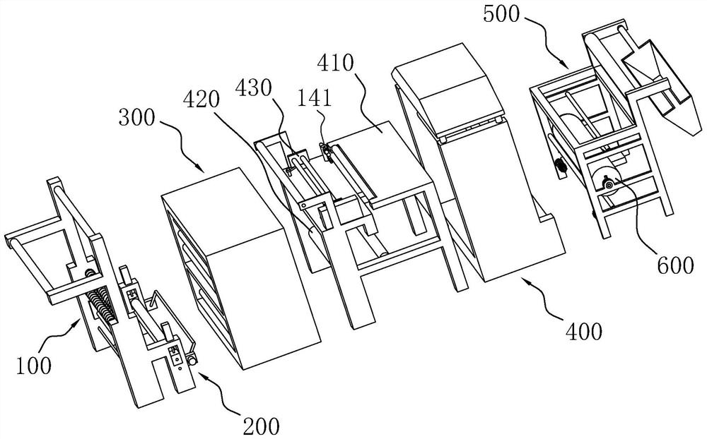
[0050] Embodiment 1: a kind of transfer printing machine, such as figure 1 and figure 2As shown, along the conveying direction of the cloth 10, the opening device 100, the feeding device 200, the photoelectric weft adjustment device 300, the printing device 400 and the receiving device 500 are sequentially included, and the cloth 10 and the transfer paper 20 are in the figure 1 Indicated by a dotted line.

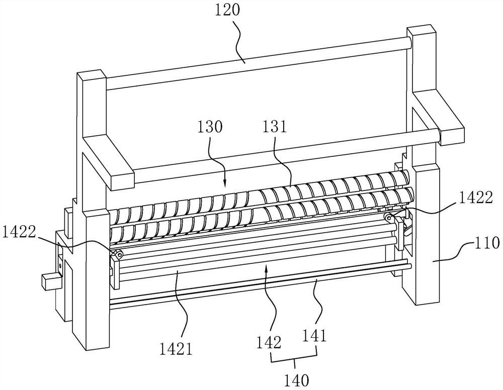
[0051] like image 3 As shown, the opening device 100 includes an opening frame 110, a lifting roller 120, an opening roller group 130 and an initial deviation correction mechanism 140, the lifting roller 120 is arranged on the top of the opening frame 110, and the opening roller group 130 includes two And the above double helical rollers 131, take three double helical rollers 131 as example in this example, three double helical rollers 131 are arranged in parallel, and two double helical rollers 131 are positioned on the same vertical plane, another double helical rolle...

Embodiment 2

[0068] Embodiment 2: as Figure 8 and Figure 9 As shown, the difference from Embodiment 1 is that the structure of the cooling roller 600 is different. In this embodiment, the two rotating shafts 620 of the cooling roller 600 are jointly connected with a water inlet pipe 624, and the middle of the water inlet pipe 624 is located at the middle position of the roller 610. A partition plate 6243 is provided at the location, and water outlet holes 6244 are arranged on the side walls of the water inlet pipe 624 on both sides of the partition board 6243. The axes are evenly distributed.


PUM


Abstract

The invention relates to the technical field of printing equipment, in particular to a transfer printing machine. The transfer printing machine comprises a printing device, and further comprises an unfolding device and a feeding device; the unfolding device is used for unfolding cloth and arranged at the feeding end of the printing device; and the feeding device is located between the unfolding device and the printing device and comprises a driving roller, a driven roller and a swing rod, wherein the driving roller and the driven roller abut against each other, and the swing rod is used for controlling the rotating speed of the driving roller through a swing angle. According to the transfer printing machine, continuous cloth conveying without shutdown can be achieved, the production efficiency is effectively improved, and the production cost is reduced.

Description

technical field [0001] The present application relates to the technical field of printing equipment, in particular to a transfer printing machine. Background technique [0002] In the textile field, the transfer printing machine transfers the printing on the transfer paper to the cloth by means of heating and pressure. Existing transfer printing machines mostly include two parts: feeding and receiving. The feeding part is in the form of coiled material, that is, the cloth is pulled out from the rolled state and sent to the receiving part after the transfer is completed. This has relatively large limitations. For example, for some fabrics that need to be pretreated, they need to be rewound before cutting after pretreatment, which will increase the process. Moreover, due to the use of the coil material loading method, it is necessary to stop the machine to change the coil after the fabric on the coil material is used up, which will also cause a waste of time and cost. In addi...

Claims


Application Information

Patent Timeline
Patent Type & Authority Applications(China)
IPC IPC(8): B41F16/02B41F23/04B65H23/025B65H23/26
CPCB41F16/02B41F23/04B65H23/025B65H23/26
Inventor 王宝孙兴广
Owner 绍兴柯桥兰嵋数码纺织科技有限公司
Learn More