Supercharge Your Innovation With Domain-Expert AI Agents!

A computer vision-based rocket motor polarity test method and system

A rocket engine and computer vision technology, applied in rocket engine installations, machines/engines, mechanical equipment, etc., can solve problems such as the gap between test effectiveness and coverage, poor traceability, and small nozzle swing, and achieve real-time accuracy. The effect of polar optical flow field prediction, low power consumption, and improved operating speed

Active Publication Date: 2022-01-04
BEIJING INST OF ASTRONAUTICAL SYST ENG
View PDF19 Cites 0 Cited by
  • Summary
  • Abstract
  • Description
  • Claims
  • Application Information

AI Technical Summary

Problems solved by technology

The swing of each nozzle is small and the swing speed is fast, and the engines of all levels are located on different floors. It is difficult for human eyes to effectively observe the overall process on the spot at the same time, judge whether the swing direction of each nozzle is correct, and test the effectiveness and coverage. There are gaps and traceability, and the lessons learned are also very painful

Method used


Image

  • A computer vision-based rocket motor polarity test method and system
  • A computer vision-based rocket motor polarity test method and system
  • A computer vision-based rocket motor polarity test method and system

Examples


Embodiment Construction

[0027]Exemplary embodiments of the present disclosure will be described in more detail below with reference to the accompanying drawings. Although exemplary embodiments of the present disclosure are shown in the drawings, it should be understood that the present disclosure may be embodied in various forms and should not be limited by the embodiments set forth herein. Rather, these embodiments are provided for more thorough understanding of the present disclosure and to fully convey the scope of the present disclosure to those skilled in the art. It should be noted that, in the case of no conflict, the embodiments of the present invention and the features in the embodiments can be combined with each other. The present invention will be described in detail below with reference to the accompanying drawings and examples.

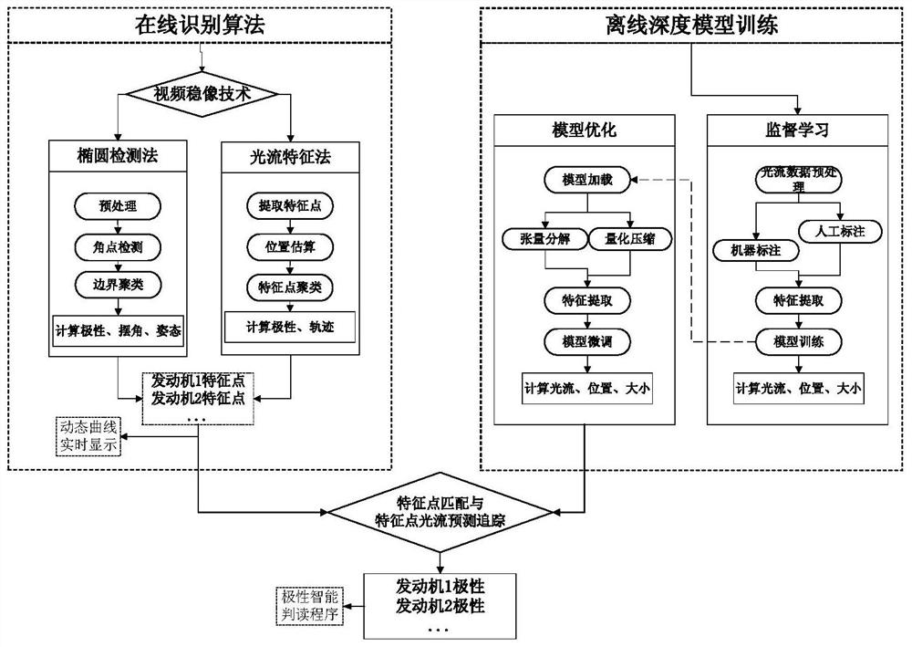
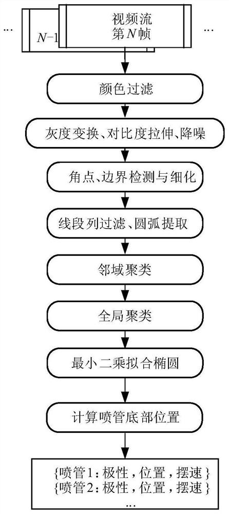
[0028] figure 1 It is a flow chart of the computer vision-based rocket motor polarity test method provided by the embodiment of the present invention. Such a...


PUM


Abstract

The invention discloses a computer vision-based rocket engine polarity test method and system, the method comprising the following steps: forming a shake smooth image; fitting and extracting the smooth image of the rocket launching nozzle after removing the shake formed by camera movement The outline and feature points in the image; get the rough position of the rocket nozzle; get the trained polar optical flow prediction model through offline training; simplify and compress the trained polar optical flow prediction model to get the polar discriminant light that can run in real time flow model; according to the polar optical flow prediction model that can be run in real time, the polar discriminant optical flow field of the smooth image that removes the jitter caused by camera movement is obtained; the moving optical flow of the rocket nozzle is obtained, and the moving light passing through the rocket nozzle The integration of the flow over time yields the polarity of motion of the rocket nozzle. The invention effectively improves the running speed, accuracy and expandability of the polarity discrimination system.

Description

technical field [0001] The invention belongs to the field of image recognition and the technical field of rocket launch reliability assurance, and in particular relates to a computer vision-based rocket engine polarity test method and system. Background technique [0002] The launch vehicle controls the attitude of the pitch, yaw and roll rocket through the swing of the engine nozzles at all stages. When the control system issues instructions to change the direction of the nozzle through multiple servo devices so that it is no longer parallel to the flight direction of the rocket, the high-speed gas injected downward from the nozzle of the engine will generate a corresponding torque to change the attitude of the rocket. The polarity test of the engine involves a test exercise of the entire loop control process from the inertial device to the control command, from the control command to the servo mechanism, from the servo mechanism to the swing direction of the nozzle. The n...

Claims


Application Information

Patent Timeline
Patent Type & Authority Patents(China)
IPC IPC(8): F02K9/96F02K9/97
CPCF02K9/96F02K9/97
Inventor 王冠张恒易航刘巧珍何巍李聃徐昊李璨耿辉王伟朱骋吉彬刘存秋黄晨张素明徐晨吕明
Owner BEIJING INST OF ASTRONAUTICAL SYST ENG
Features
  • R&D
  • Intellectual Property
  • Life Sciences
  • Materials
  • Tech Scout
  • Unparalleled Data Quality
  • Higher Quality Content
  • 60% Fewer Hallucinations
Learn More