
Evaporator assembly and wall-mounted air conditioner

An evaporator assembly and evaporator technology, applied in air conditioning systems, heating methods, space heating and ventilation, etc., can solve problems such as easy water blowing, and achieve the effect of avoiding deterioration

Active Publication Date: 2022-03-29
HEFEI HAIER AIR CONDITIONER
View PDF6 Cites 0 Cited by
  • Summary
  • Abstract
  • Description
  • Claims
  • Application Information

AI Technical Summary

Problems solved by technology

[0004] In order to solve the above problems in the prior art, that is, to solve the problem that the existing wall-mounted air conditioner is easy to blow water when the humidity is high, the present invention provides an evaporator assembly for the wall-mounted air conditioner, the evaporator The evaporator assembly includes an evaporator body, a first tube sheet installed at the first end of the evaporator body, and a second tube sheet installed at the second end of the evaporator body, and the inner surface of the evaporator body is opened There are a plurality of diversion grooves, and the diversion grooves extend along the length direction of the evaporator body. When the wall-mounted air conditioner is hung on the wall, the length direction of the evaporator assembly and the horizontal direction The direction has a certain included angle, so that the first end of the evaporator body is lower than the second end, and the condensed water can flow out from the guide groove along the direction from the second end to the first end of the evaporator body

Method used


Image

  • Evaporator assembly and wall-mounted air conditioner
  • Evaporator assembly and wall-mounted air conditioner
  • Evaporator assembly and wall-mounted air conditioner

Examples


Embodiment 1

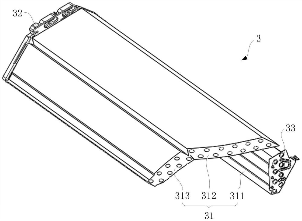
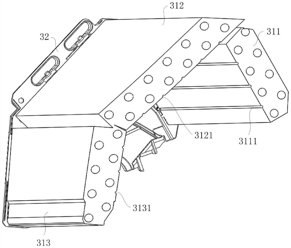
[0049] First refer to figure 1 and figure 2 , to describe the evaporator assembly of the present invention. in, figure 1 It is a structural diagram (1) of the evaporator assembly of the present invention; figure 2 It is a structural diagram of the evaporator assembly of the present invention after removing the second tube sheet and the deflector column.

[0050] like figure 1 and figure 2 As shown, in order to solve the problem that the existing wall-mounted air conditioner is easy to blow water when the humidity is high, the evaporator assembly 3 of the present application includes an evaporator body 31 and a first end installed on the evaporator body 31 (i.e. figure 1 The first tube plate 32 in the upper left end of the center) and the second end installed on the evaporator body 31 (ie figure 1 The second tube plate 33 at the lower right end of the center), the inner surface of the evaporator body 31 is provided with a plurality of diversion grooves (see figure 2 ...

Embodiment 2

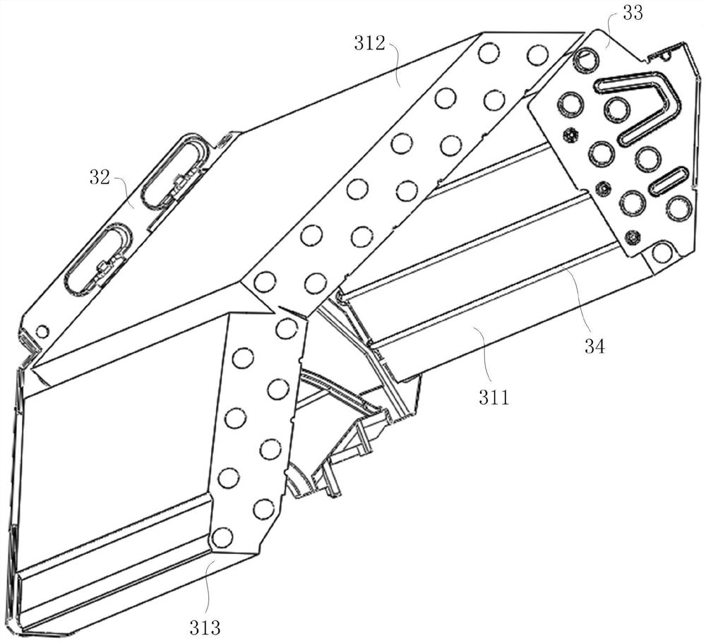
[0059] Refer below image 3 , Figure 10-12 , to describe the second embodiment of the evaporator assembly of the present application. in, image 3 It is the structural diagram (2) of the evaporator assembly of the present invention; Figure 10 It is a partial enlarged view of the evaporator assembly of the present invention at the first tube sheet; Figure 11 It is a partial enlarged view of the evaporator assembly of the present invention at the second tube sheet; Figure 12 It is a structural diagram of the second tube sheet of the present invention.

[0060] First refer to image 3 , under the condition that the other arrangements of Embodiment 1 remain unchanged, the evaporator assembly 3 further includes a guide column 34 arranged in the guide groove. The guide column 34 will be described below with reference to the first evaporator 311 , but those skilled in the art know that the arrangement of the guide column 34 can also be applied to the second evaporator 312 a...

Embodiment 3

[0065] Combine below Figure 13-16 , to describe the wall-mounted air conditioner of the present application. in, Figure 13 It is a structural diagram of the wall-mounted air conditioner of the present invention; Figure 14 It is a rear view of the wall-mounted air conditioner of the present invention in an installed state; Figure 15 It is a partially enlarged view of the wallboard of the present invention; Figure 16 It is a partially enlarged view of the back of the skeleton of the wall-mounted air conditioner of the present invention.

[0066] like Figure 13-14As shown, the application also provides a wall-mounted air conditioner, which includes a housing 1, a skeleton 2, and an axial flow fan 4 (refer to Figure 8 ) and the evaporator assembly 3 described in Embodiment 1 or Embodiment 2 above. Wherein, an air inlet 11 and an air outlet 12 are formed on the casing 1, an axial flow fan 4 is installed on the frame 2, and an evaporator assembly 3 is arranged on the ou...


PUM


Abstract

The invention relates to the technical field of air conditioning, in particular to an evaporator assembly and a wall-mounted air conditioner. The invention aims to solve the problem that the existing wall-mounted air conditioner is easy to blow water when the humidity is high. For this purpose, the evaporator assembly of the present invention comprises an evaporator body and a first tube sheet mounted on a first end of the evaporator body and a second tube sheet mounted on a second end of the evaporator body, the inner body of the evaporator body There are multiple diversion grooves on the side, and the diversion grooves extend along the length direction of the evaporator body. When the wall-mounted air conditioner is hung on the wall, the length direction of the evaporator assembly has a certain angle with the horizontal direction. Therefore, the first end of the evaporator body is lower than the second end, and the condensed water can flow out from the guide groove along the direction from the second end to the first end of the evaporator body. By providing a plurality of diversion grooves on the inner surface of the evaporator body, when the evaporator is arranged obliquely, the condensed water deposited on the evaporator can flow out of the evaporator along the diversion grooves.

Description

technical field [0001] The invention relates to the technical field of air conditioning, in particular to an evaporator assembly and a wall-mounted air conditioner. Background technique [0002] When the indoor unit of the existing wall-mounted air conditioner is running, if the indoor environment humidity is high, condensed water will be generated on the evaporator. Although the current indoor unit housing is provided with a water tray, it is still impossible to avoid the condensed water dripping On the cross-flow fan, driven by the cross-flow fan, the condensed water will be blown out from the air outlet, causing the air conditioner to "blow water" and seriously affect the user experience. [0003] Correspondingly, a new evaporator assembly and a wall-mounted air conditioner are needed in the art to solve the above problems. Contents of the invention [0004] In order to solve the above problems in the prior art, that is, to solve the problem that the existing wall-moun...

Claims


Application Information

Patent Timeline
Patent Type & Authority Patents(China)
IPC IPC(8): F24F1/0063F24F1/0057F24F13/22
CPCF24F1/0063F24F1/0057F24F13/222
Inventor 李涛张立智刘丙磊韩涛
Owner HEFEI HAIER AIR CONDITIONER
Learn More