Circuit integrated electric meter box

A technology of electric meter boxes and lines, which is applied in the field of electric meter boxes, can solve problems such as irregularities and no integrated effect of lines, and achieve the effect of regular wiring and good integrated effects

Active Publication Date: 2021-02-19
成都民达电力设备有限公司
View PDF6 Cites 2 Cited by
  • Summary
  • Abstract
  • Description
  • Claims
  • Application Information

AI Technical Summary

Problems solved by technology

[0003] At present, when the existing meter box is used, multiple meters are directly installed inside the meter box body, and the connecting wires at the bottom are exposed at the bottom of the meter body, so that the circuit does not have a good The integrated effect is irregular, therefore, it is urgent to set up a line integrated meter box to solve such problems

Method used


Image

  • Circuit integrated electric meter box
  • Circuit integrated electric meter box
  • Circuit integrated electric meter box

Examples


Embodiment 1

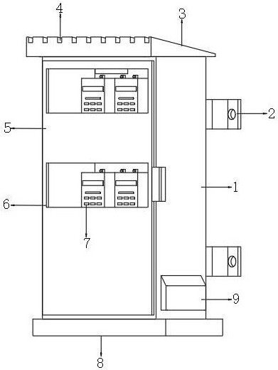
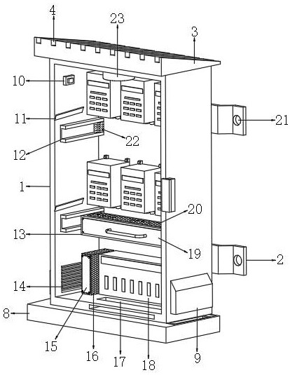
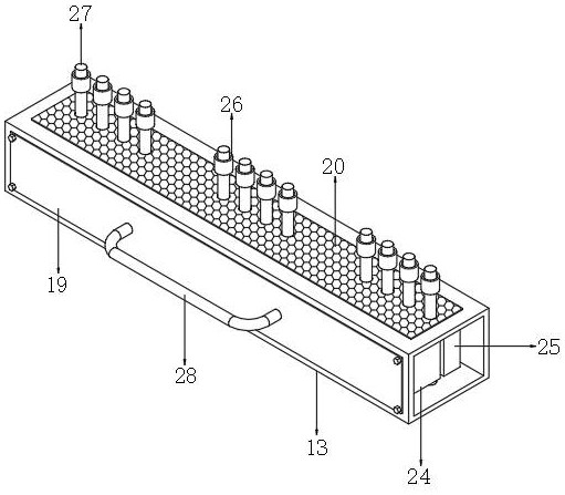
[0035]A line integrated meter box, such as Figure 1-7 As shown, including the meter box body 1, one side inner wall of the meter box body 1 is connected with multiple columns of equidistantly distributed meter bodies 7 by bolts, and the bottom of the meter body 7 is connected with equidistantly distributed wiring pipes 26 by bolts, The other side of the meter box body 1 is hinged with a box door 5, and one side of the box door 5 is provided with a plurality of observation windows 6, the positions of the observation windows 6 correspond to the positions of the meter body 7, and the inner walls of both ends of the meter box body 1 A plurality of limit frames 12 are welded, and the same wiring frame 13 is clamped between the sides of the two limit frames 12. There are multiple groups of equidistantly distributed wires 27 passing through the inside of the wiring frame 13. 27 passes through the inside of the wiring pipe 26 and is connected to the meter body 7. There is an inlet gr...

Embodiment 2

[0046] A line integrated meter box, such as Figure 8 As shown, in order to solve the problem of electric leakage in the meter box; this embodiment makes the following improvements on the basis of embodiment 1: one side of the water storage tank is provided with a transparent window 39 that runs through the base 8, and the inner wall of the transparent window 39 is connected by bolts There is a transparent plate, one side of the water storage tank is welded with a slant plate 38, the bottom of the slant plate 38 is in contact with the top of the sponge 37, polyaniline powder 40 is filled between the slant plate 38, the sponge 37 and the transparent plate.

[0047] When this embodiment is in use, when the rainwater is stored in the water storage tank through the sponge 37, the rainwater will enter the inside of the sponge 37, the transparent plate and the inclined plate 38 and mix with the polyaniline powder 40 to form a polyaniline solution. When the main body 1 leaks electric...


PUM


Abstract

The invention discloses a circuit integrated electric meter box. The circuit integrated electric meter box comprises an electric meter box body, wherein multiple columns of electric meter bodies distributed at equal intervals are fixed to the inner wall of one side of the electric meter box body; wiring pipes distributed at equal intervals are fixed to the bottoms of the electric meter bodies; a box door is hinged to the other side of the electric meter box body; a plurality of observation windows are formed in one side of the box door; the positions of the observation windows correspond to the positions of the electric meter bodies; a plurality of limiting frames are fixed to the inner walls of the two ends of the electric meter box body; and the same wiring frame is clamped between the sides, opposite to the two limiting frames, of the electric meter box body. According to the invention, a first clamping seat and a second clamping seat are used for fixing wires, thereby preventing the wires in the electric meter box body from being directly exposed at the bottom of the electric meter bodies and enabling circuits to be better in integration effect; and wiring is regular, the bottom and interior of the electric meter box body can be cooled, and the interior of the electric meter box body can be sterilized.

Description

technical field [0001] The present invention relates to the technical field of electric meter boxes, in particular to a circuit-integrated electric meter box. Background technique [0002] The meter box is used to protect electrical components and install and fix electrical components. Its main components are ABS engineering plastics, polycarbonate transparent PC materials, DMC, and SMC. It is made of injection molding and pressing. According to the use classification, there are public grids Cable branch boxes, low-voltage distribution boxes, street lamp and traffic light control boxes, multi-function metering boxes, integrated distribution boxes, and wall-mounted distribution boxes, etc. [0003] At present, when the existing meter box is used, multiple meters are directly installed inside the meter box body, and the connecting wires at the bottom are exposed at the bottom of the meter body, so that the circuit does not have a good The integration effect is irregular, ther...

Claims


Application Information

Patent Timeline
Patent Type & Authority Applications(China)
IPC IPC(8): G01R11/04A61L2/08G01R11/25
CPCA61L2/088G01R11/04G01R11/25
Inventor 张悦王巧年
Owner 成都民达电力设备有限公司
Why Eureka
Try Eureka