Stator punching sheet, stator and motor

A stator punching and stator technology, which is applied in the direction of electrical components, electromechanical devices, electric components, etc., can solve the problems of poor uniformity of magnetic density at the teeth and low filling rate of stator slots, and achieve the effect of uniform magnetic density

Inactive Publication Date: 2021-02-19
QINGDAO CCS ELECTRIC CORP
View PDF4 Cites 0 Cited by
  • Summary
  • Abstract
  • Description
  • Claims
  • Application Information

AI Technical Summary

Problems solved by technology

[0006] The purpose of the present disclosure is to provide a stator punch, a stator and a motor, so as to im

Method used


Image

  • Stator punching sheet, stator and motor
  • Stator punching sheet, stator and motor
  • Stator punching sheet, stator and motor

Examples


Embodiment Construction

[0025] The following will clearly and completely describe the technical solutions in the embodiments of the present disclosure with reference to the accompanying drawings in the embodiments of the present disclosure. Apparently, the described embodiments are part of the embodiments of the present disclosure, but not all of them. Based on the implementation manners in the present disclosure, all other implementation manners obtained by those skilled in the art without creative efforts fall within the protection scope of the present disclosure.

[0026] Specific embodiments of the present disclosure will be described in detail below in conjunction with the accompanying drawings.

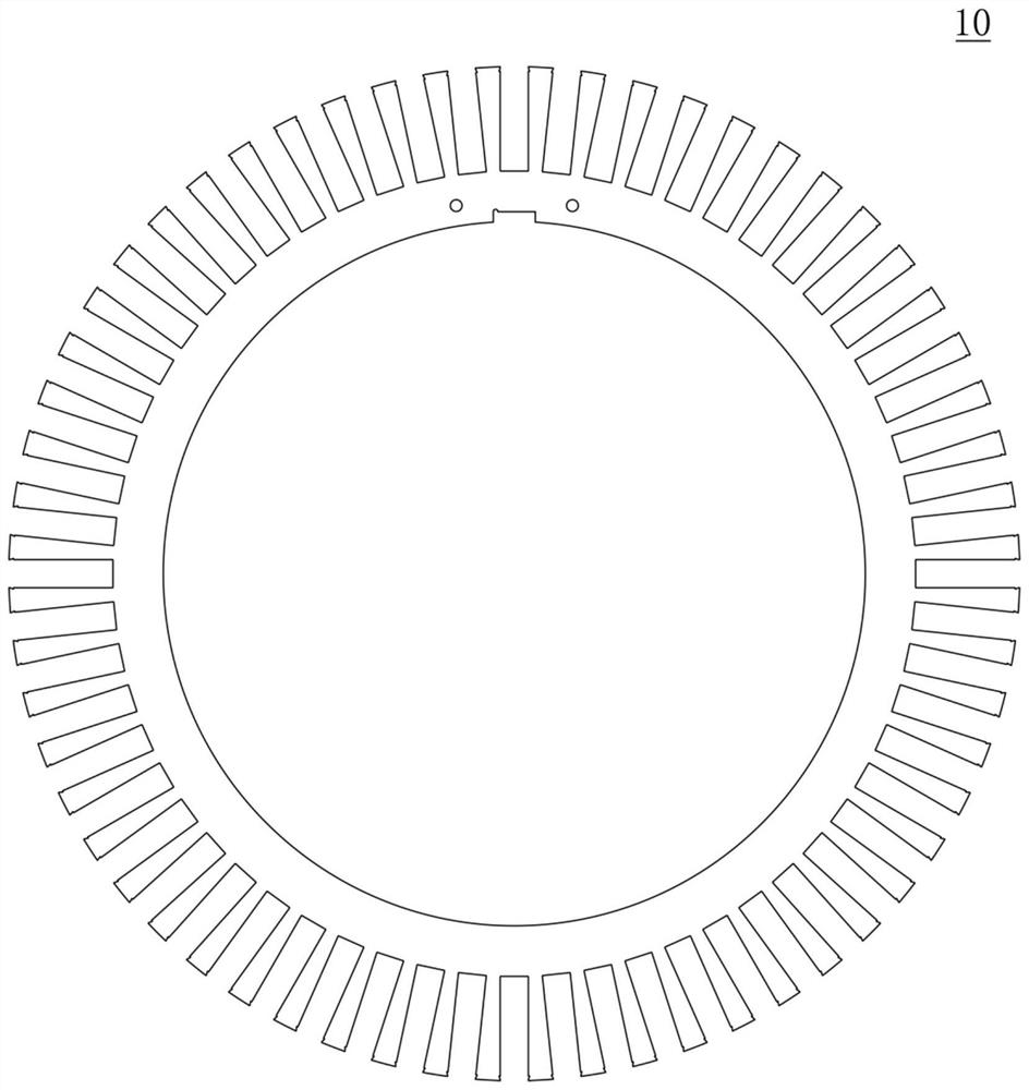
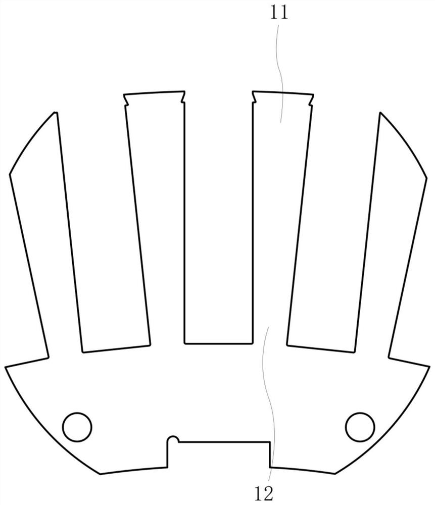
[0027] Figure 5 is a view showing a stator punching according to an exemplary embodiment of the present disclosure, Figure 6 is a partial enlarged view showing stator teeth and stator slots of a stator blank according to an exemplary embodiment of the present disclosure.

[0028] In a first aspect,...


PUM


Abstract

The present invention relates to a stator punching sheet, a stator, and a motor, in which the stator punching sheet may comprise: a stator yoke part having an annular shape; and stator tooth parts which are arranged at intervals in the circumferential direction of the stator yoke part, wherein stator slots are formed between adjacent stator tooth parts, each stator tooth part is provided with an inner tooth part and an outer tooth part which extend in the radial direction of the stator, and a bent structure is formed at the joint of each inner tooth part and the corresponding outer tooth part,and therefore, the stator slots formed between the adjacent stator tooth parts have stepped slot types. The stator punching sheet, the stator and the motor have the advantages that on one hand, the formed coil can be assembled, so that the slot fullness rate of stator slots can be improved, and the utilization rate of materials can be increased; and on the other hand, the stator punching sheet with the stepped stator slots is provided with the stator tooth parts with uniform tooth width, so that the magnetic density of the stator tooth parts can be more uniform.

Description

technical field [0001] The present disclosure relates generally to the field of electric machine construction. More specifically, the present disclosure relates to a stator blank, a stator and an electric machine. Background technique [0002] The stator slots of the motor stator can be divided into parallel slots and pear-shaped slots according to the type of coils assembled, and the parallel slots are generally used to assemble formed coils, such as figure 1 and figure 2 shown; while pear-shaped slots are generally used to assemble loose embedded coils, such as image 3 and Figure 4 shown. [0003] Scatter-embedded coils are usually coils made of round enameled wires. The disadvantages of this coil are: on the one hand, the insulation performance is not as good as that of formed coils, especially for high-voltage motors. The insulation performance of scattered-embedded coils is much lower than that of formed coils; On the one hand, affected by the manufacturing proc...

Claims


Application Information

Patent Timeline
IPC IPC(8): H02K1/14H02K1/16
CPCH02K1/146H02K1/165
Inventor 宋承林杜爱娟孙即明丁军华
Owner QINGDAO CCS ELECTRIC CORP
Why Eureka
Try Eureka