A double-coil radial spherical magnetic bearing

A magnetic bearing and double coil technology, applied in the direction of bearings, shafts and bearings, mechanical equipment, etc., can solve the problems of increasing the torsional bearing load of the flywheel, uneven electromagnetic force, affecting the uniformity of magnetic density, etc., to eliminate radial translation. interference, improve the current response rate, improve the effect of control accuracy

Active Publication Date: 2018-09-14
BEIHANG UNIV
View PDF3 Cites 0 Cited by
  • Summary
  • Abstract
  • Description
  • Claims
  • Application Information

AI Technical Summary

Problems solved by technology

However, when the rotor deflects, the magnetic air gap between the stator and rotor of the magnetic bearing is uneven, resulting in uneven electromagnetic force in the magnetic pole surface, thereby generating a torsional moment relative to the center of mass of the rotor, that is, the translation control produces an interference torque to the torsion control
The permanent magnet bias radial magnetic bearing described in Chinese Patent No. 201010256248.6 and 200710065049.5 and the radial magnetic bearing with pole shoes described in 201010226322. Uneven air gap, resulting in a large negative torsional moment, which increases the load on the torsional bearing of the flywheel, thereby reducing the control accuracy and control torque accuracy of the flywheel rotor, and the angle of the pole shoe is very small, which is prone to local magnetic density of the iron core Saturation phenomenon, and will affect the uniformity of magnetic density distribution along the circumference, which will indirectly lead to the reduction of control accuracy

Method used


Image

  • A double-coil radial spherical magnetic bearing
  • A double-coil radial spherical magnetic bearing
  • A double-coil radial spherical magnetic bearing

Examples


Embodiment Construction

[0016] specific implementation

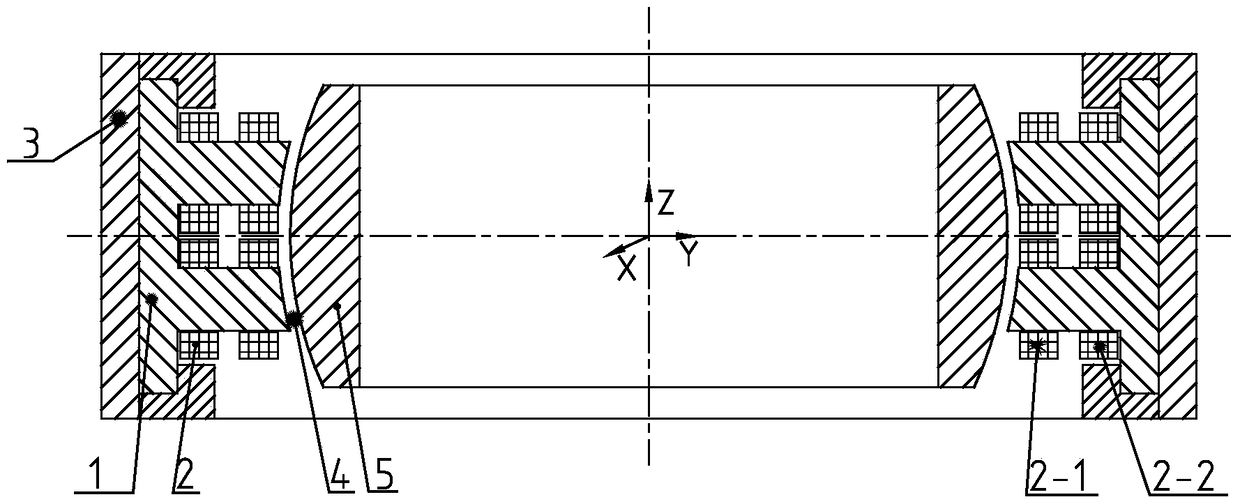
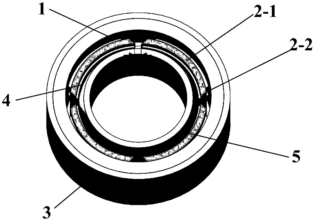
[0017] like figure 1 and figure 2 As shown, a double-coil radial spherical magnetic bearing mainly includes: four stator cores (1), coils (2), sleeves (3), air gaps ( 4) and the rotor (5). The radial bearing coils (2) are wound on the two magnetic poles of each stator iron core (1), and the radial inner side of the four stator iron cores (1) is the rotor (5), the stator iron cores (1) and the A radial magnetic air gap (4) is formed between the rotors (5), the radial outer side of the stator core (1) is a sleeve (3), and a coil (2) wound on the magnetic pole of each stator core (1) ) comprises a first excitation coil (2-1) and a second excitation coil (2-2), wherein the first excitation coil (2-1) is close to the air gap (4) side, and the second excitation coil (2-2) is close to the air gap (4) side At the root of the magnetic pole, the number of turns of the first excitation coil (2-1) is 20 to 50 turns, preferably 28 turns, and its contro...


PUM


Abstract

The invention discloses a double-coil radial and spherical magnetic bearing. The double-coil radial and spherical magnetic bearing mainly comprises four stator cores arranged in the + / - X direction and the + / - Y direction, a first coil, a second coil, a sleeve, an air gap and a rotor. By adopting the spherical magnetic bearing structure, the electromagnetic force exerted on a rotation shaft always passes through the sphere center, when the sphere center of the rotation shaft coincides with the mass center, the torque generated by the electromagnetic force relative to the rotation shaft is zero, and therefore interference of radial twisting to axial translation is removed. In addition, by adopting the specific pole shoe structure in the stator cores, magnetic field distribution is more uniform in the peripheral direction; the double-coil structure is adopted in field coils of the stator cores, the turns of the two coils are different, the current of the coil smaller in turn is controllable, the current of the coil higher in turn is unchangeable, and the current response rate is increased compared with the single-coil structure; the differential mode is adopted in the controllable current, so that the control accuracy of the magnetic bearing is further improved.

Description

technical field [0001] The invention relates to a non-contact radial magnetic suspension bearing, in particular to a spherical magnetic bearing with double coils, which can be used as a non-contact support for rotating parts in small spacecraft, and is especially suitable for non-contact magnetic suspension flywheels or magnetic suspension control torque gyroscopes. Contact support. technical background [0002] With the development of aerospace technology, spacecraft such as satellites and space stations have higher and higher requirements for attitude control, and traditional mechanical momentum wheels can no longer meet the requirements. The magnetic suspension flywheel is supported by magnetic bearings, which eliminates the wear caused by mechanical bearings and improves the precision and stability of the control torque. [0003] In the existing magnetic levitation flywheel or magnetic levitation control torque gyro structure, a radial magnetic bearing with two degrees ...

Claims


Application Information

Patent Timeline
Patent Type & Authority Patents(China)
IPC IPC(8): F16C32/04
Inventor 孙津济马辛刘刚汤继强韩伟涛
Owner BEIHANG UNIV
Why Eureka
Try Eureka