A Permanent Magnet Motor with Reduced Pole Frequency and Slot Frequency Radial Electromagnetic Exciting Force

A technology of electromagnetic excitation force and permanent magnet motor, which is applied to the static parts of the magnetic circuit, the rotating parts of the magnetic circuit, and the shape/style/structure of the magnetic circuit. and power density, the effect of the chute is not obvious, etc., to achieve the effect of reducing vibration and noise, reducing mechanical vibration and noise, reducing deformation and vibration

Active Publication Date: 2018-05-11
TSINGHUA UNIV
View PDF4 Cites 0 Cited by
  • Summary
  • Abstract
  • Description
  • Claims
  • Application Information

AI Technical Summary

Problems solved by technology

These three types of electromagnetic exciting forces are caused by the nature of motors and power electronic devices, and it is extremely difficult to reduce and weaken these electromagnetic exciting forces
For the first type of electromagnetic excitation force, the existing method can only be realized by reducing the air gap flux density of the motor, but this method will reduce the torque and power density of the motor
For the second type of electromagnetic excitation force, inclined grooves or closed grooves are often used, but the effect of inclined grooves is not obvious, and the process is complicated; closed grooves will increase the leakage resistance of the groove, and the effect is not obvious
For the third type of electromagnetic excitation force, the existing method is to increase the filter circuit, reduce the harmonics related to the switching frequency or increase the switching frequency, but adding the filter circuit increases the weight of the equipment and reduces the reliability; increasing the switching frequency will Increase loss, reduce efficiency
It can be seen that so far, there is no better solution to the vibration and noise of the motor.

Method used


Image

  • A Permanent Magnet Motor with Reduced Pole Frequency and Slot Frequency Radial Electromagnetic Exciting Force
  • A Permanent Magnet Motor with Reduced Pole Frequency and Slot Frequency Radial Electromagnetic Exciting Force
  • A Permanent Magnet Motor with Reduced Pole Frequency and Slot Frequency Radial Electromagnetic Exciting Force

Examples


Embodiment Construction

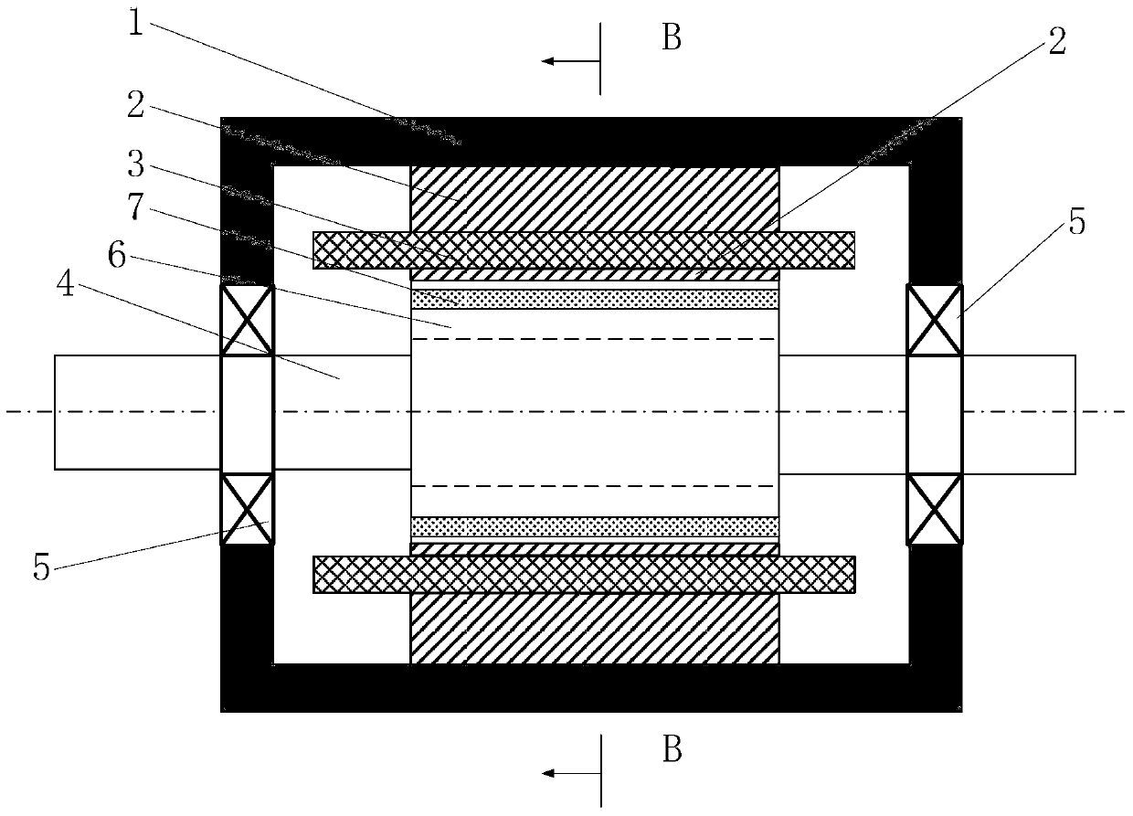
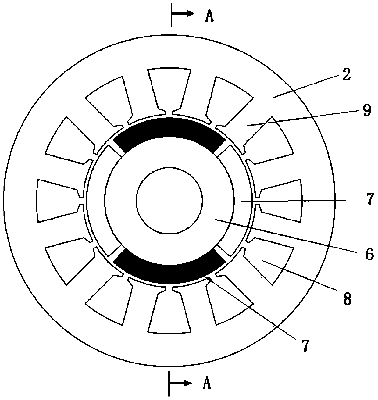
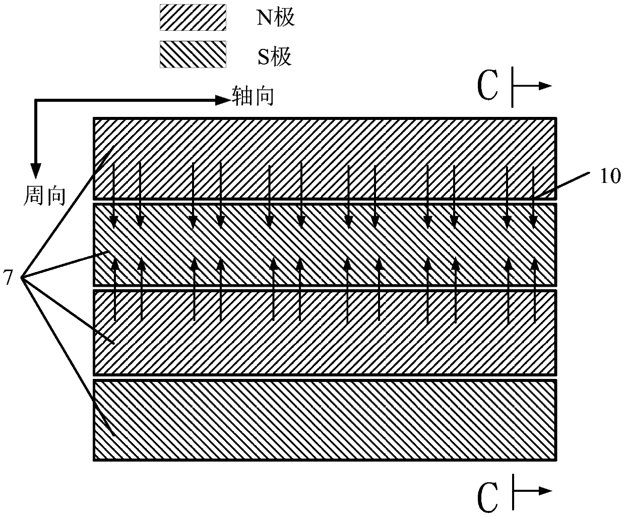
[0026] Such as Figure 1 ~ Figure 3 As shown, the permanent magnet motor includes a stator base 1 , a stator core 2 , a stator winding 3 , a permanent magnet 7 , a rotor core 6 , a rotor shaft 4 and a bearing 5 . A stator core 2 is fixed inside the stator frame 1, and a stator winding 3 is arranged on the stator core 2; wherein, the stator frame 1 can be fixed by a conventional motor installation method, and the stator core 2 is a part of the magnetic circuit of the motor , The stator winding 3 is generally a three-phase winding. The rotor shaft 4 is fixedly arranged in the stator frame 1 through the bearing 5, and the rotor core 6 is fixedly arranged on the rotor shaft 4, and a permanent magnet 7 is arranged on the rotor iron core 6, and the magnetization direction of the permanent magnet 7 is radial, The polarities of the permanent magnets 7 are alternately arranged, and the rotor shaft 4 can drive the rotor core 6 and the permanent magnets 7 to rotate around the axis. Whe...


PUM


Abstract

The invention relates to a permanent magnet motor which reduces the radial electromagnetic excitation force of the pole frequency and the slot frequency. The bearing is fixedly arranged in the stator frame, the rotor iron core is fixedly arranged on the rotor shaft, and the permanent magnet is arranged on the rotor iron core. The permanent magnets are composed of permanent magnets arranged in the same axial direction and permanent magnets arranged alternately in the axial direction; the magnetization direction of the permanent magnets arranged in the axial direction and the permanent magnets arranged in the axial direction are radial, and the polarity of the permanent magnets arranged in the axial direction is alternately arranged , forming the interaction between the magnetic poles and the stator to generate torque and radial electromagnetic force; the permanent magnets arranged alternately in the axial direction are composed of several small permanent magnets segmented along the axial direction, and the small permanent magnets are arranged on two adjacent axes along the circumferential direction Between the consistent arrangement of permanent magnets, the small pieces of permanent magnets along the axial direction are arranged alternately in polarity. The invention can reduce the extreme frequency radial electromagnetic excitation force, reduce mechanical vibration and noise.

Description

technical field [0001] The invention relates to a permanent magnet motor, in particular to a permanent magnet motor capable of reducing the radial electromagnetic excitation force of pole frequency and slot frequency. Background technique [0002] Modern society cannot do without motors, and motors are used in transportation, industrial and agricultural production, information processing, and various fields of daily life. There are many types of motors with different structures, such as asynchronous motors, permanent magnet motors, electric excitation motors, etc. All kinds of motors will generate vibration and noise during the rotation process. Vibration noise is a kind of environmental pollution, which will have adverse effects on people's health and daily life; vibration and noise are more important in the military field. Therefore, it is of great significance to reduce the vibration and noise of the motor. [0003] The fundamental magnetic field and a series of harmoni...

Claims


Application Information

Patent Timeline
Patent Type & Authority Patents(China)
IPC IPC(8): H02K1/27H02K1/12
Inventor 王善铭孙旭东柴建云王祥珩
Owner TSINGHUA UNIV
Why Eureka
Try Eureka