A New Type of Precision Piezoelectric Injection Valve
What is AI technical title?
AI technical title is built by Patsnap AI team. It summarizes the technical point description of the patent document.
A precision piezoelectric and jet valve technology, which is applied to the device for coating liquid on the surface, coating, etc., can solve the problem of large pressure amplitude of power components and amplifying levers, inconvenient disassembly and assembly of nozzle flow channels, and nozzle Position accuracy can not be guaranteed and other problems, to achieve the effect of improving maintenance efficiency, reducing the difficulty of operation and debugging, and flexible valve body position
Active Publication Date: 2021-07-09
SHENZHEN TENSUN IND EQUIP
View PDF6 Cites 0 Cited by
Summary
Abstract
Description
Claims
Application Information
AI Technical Summary
This helps you quickly interpret patents by identifying the three key elements:
Problems solved by technology
Method used
Benefits of technology
Problems solved by technology
[0005] The purpose of the present invention is to disclose a new type of precision piezoelectric injection valve, which solves the technical problem: it is difficult to calibrate after the nozzle and the striker are worn out, even after calibration, the position of the nozzle is difficult to maintain, and it is easy to occur during work It is loose and out of position, and the flow path of the nozzle is inconvenient to disassemble and assemble, so the position accuracy of the nozzle cannot be guaranteed after repeated disassembly and assembly. The position is not flexible, which easily affects the construction efficiency. When using the screw to adjust the positional relationship between the striker and the nozzle, in the process of turning the screw, the adjustment accuracy is low, and it is easy to cause the power component and the amplifying lever to press down. It will increase the wear degree of the nozzle and the striker per unit time, and a new type of precision piezoelectric injection valve is proposed
Method used
Image
Click on the blue label to locate the original text in one second.
Reading with bidirectional positioning of images and text.
Examples
Embodiment Construction
[0035] The following will clearly and completely describe the technical solutions in the embodiments of the present invention with reference to the accompanying drawings in the embodiments of the present invention. Obviously, the described embodiments are only some, not all, embodiments of the present invention. Based on the embodiments of the present invention, all other embodiments obtained by persons of ordinary skill in the art without creative efforts fall within the protection scope of the present invention.
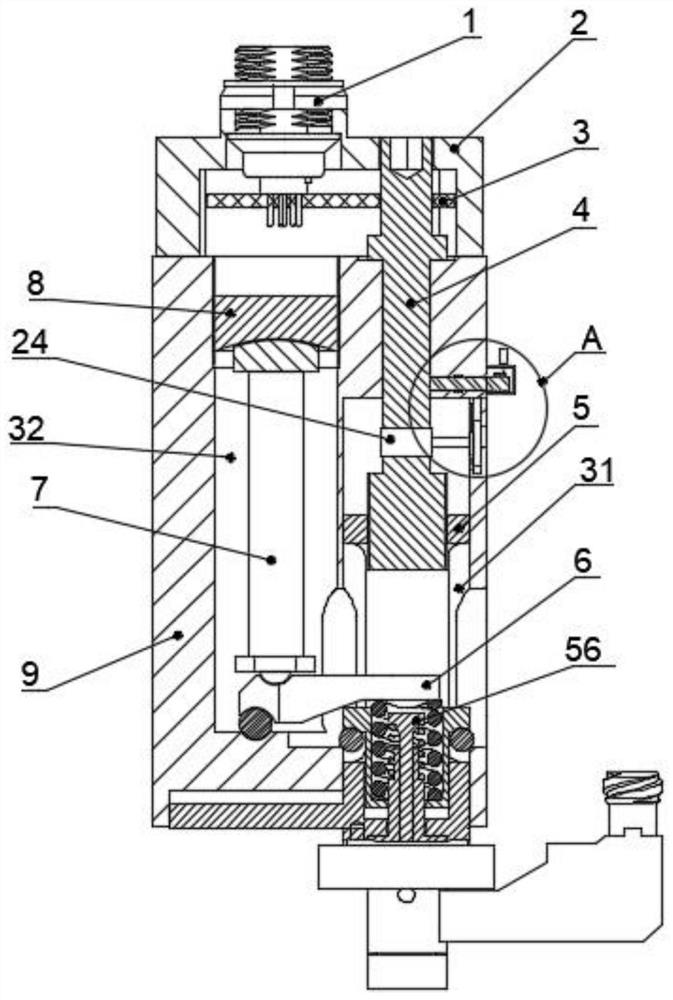
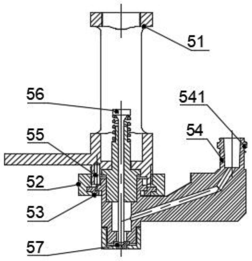
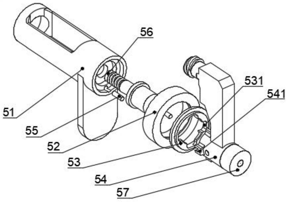
[0036] see Figure 1-11 , the present invention provides a technical solution: a new type of precision piezoelectric injection valve, including a socket 1, the socket 1 and the control board 3 are installed in the end cover 2, the end cover 2, the adjusting screw 4, the flow channel assembly 5, the amplifying lever 6. The power assembly 7 and the fixed hinge 8 are installed on the body 9, the body 9 is provided with a first cavity 31 and a second cavity 32, the flo...
PUM
Abstract
The invention discloses a novel precision piezoelectric injection valve, belonging to the technical field of piezoelectric injection valves, comprising a socket, the socket and a control board installed in an end cover, the end cover, an adjusting screw, a flow channel assembly, and an amplifying lever , power components and fixed hinges are installed on the body. In the present invention, the nozzle is fixedly installed through the cooperation of the designed end cap, adjusting screw, flow channel assembly, amplifying lever, power assembly, fixed hinge, body and knob handle, and the position of the nozzle will not be loosened after a long time of work. , prolong the interval between regular nozzle calibration, reduce maintenance time, improve the stability of continuous work, the position of the flow channel can be adjusted, and the position of the valve body is more flexible in the face of complex working environments. , to facilitate maintenance, improve maintenance efficiency, effectively improve the accuracy of the value between the striker and the nozzle, and avoid a large pressure between the striker and the nozzle.
Description
technical field [0001] The invention belongs to the technical field of piezoelectric injection valves, in particular to a novel precision piezoelectric injection valve. Background technique [0002] The injection valve uses the characteristics of piezoelectric materials to generate mechanical force through voltage. When the piezoelectric material below is charged, the valve opens, and when the piezoelectric material above is charged, the valve closes. Because the space for opening and closing the valve is very small, The action frequency is extremely high, and a very small amount of liquid material can be ejected at high speed. Known and potential technologies include piezoelectric ceramics, lever amplification mechanism, nozzle calibration, high-precision dispensing and ultra-micro-dispensing. [0003] The fields of application of piezoelectric injection valves include the electronics industry, mobile communication industry, automobile industry, photovoltaic and semiconduct...
Claims
Application Information
Patent Timeline
Application Date:The date an application was filed.
Publication Date:The date a patent or application was officially published.
First Publication Date:The earliest publication date of a patent with the same application number.
Issue Date:Publication date of the patent grant document.
PCT Entry Date:The Entry date of PCT National Phase.
Estimated Expiry Date:The statutory expiry date of a patent right according to the Patent Law, and it is the longest term of protection that the patent right can achieve without the termination of the patent right due to other reasons(Term extension factor has been taken into account ).
Invalid Date:Actual expiry date is based on effective date or publication date of legal transaction data of invalid patent.

