Shape correcting device for hardware stamping part

A technology for stamping and shape correction, which is applied in the field of metal stamping parts shape correction devices, can solve problems such as poor shape correction effect, achieve good shape correction effect, prevent movement, and be convenient to use

Pending Publication Date: 2021-02-23
CHANGSHU SHUNLI ELECTRONIC EQUIP FACTORY
View PDF0 Cites 0 Cited by
  • Summary
  • Abstract
  • Description
  • Claims
  • Application Information

AI Technical Summary

Problems solved by technology

The deformation in the direction of the thick plate is generally not considered emphatically. After the metal stamping parts are stamped, they will use the shape correction device to clean the surface. The current metal stamping parts shape correction device lacks a special shape correction device when performing shape correction, and the correction bad shape

Method used


Image

  • Shape correcting device for hardware stamping part
  • Shape correcting device for hardware stamping part
  • Shape correcting device for hardware stamping part

Examples


Embodiment Construction

[0018] The following will clearly and completely describe the technical solutions in the embodiments of the present invention with reference to the accompanying drawings in the embodiments of the present invention. Obviously, the described embodiments are only some, not all, embodiments of the present invention. Based on the embodiments of the present invention, all other embodiments obtained by persons of ordinary skill in the art without making creative efforts belong to the protection scope of the present invention.

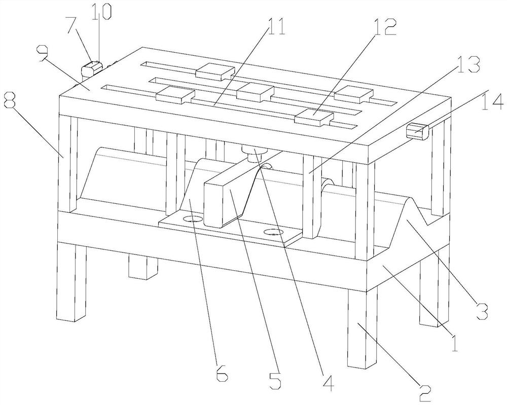
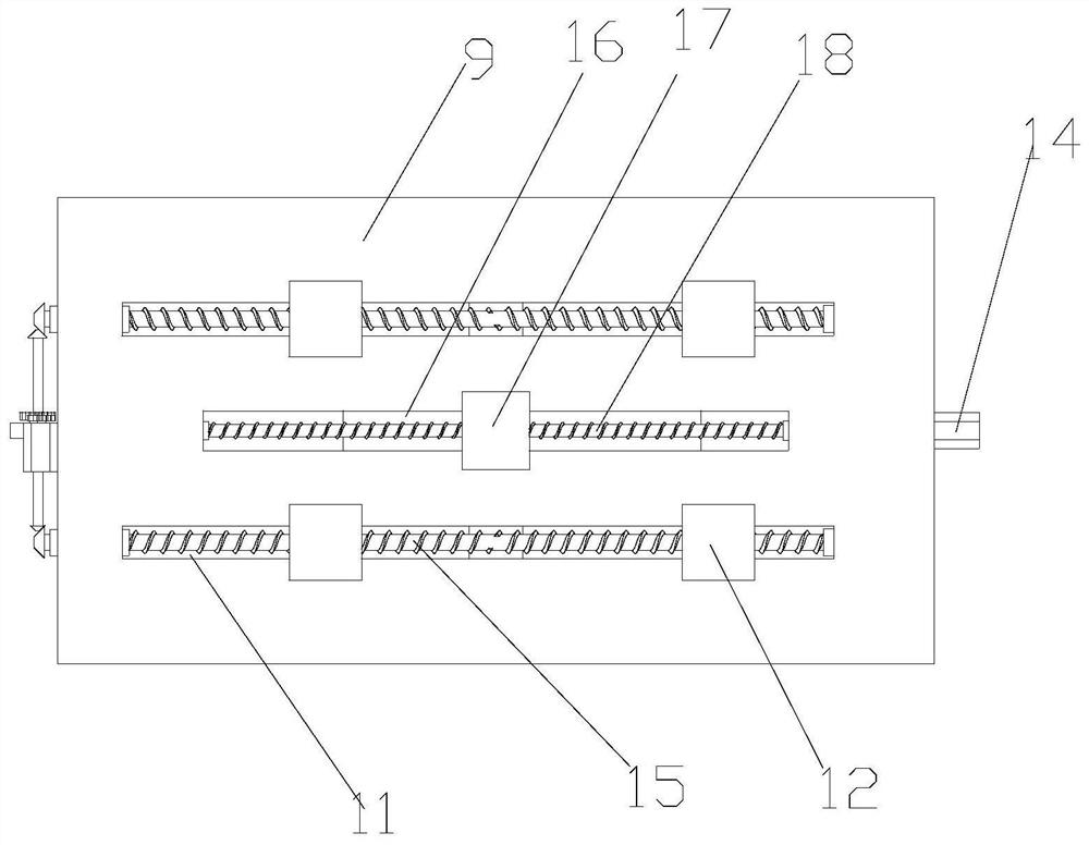
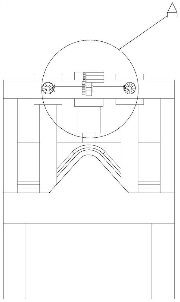
[0019] see Figure 1-4 , the present invention provides a technical solution: a metal stamping parts correction device, including a base 1, the lower end of the base 1 is provided with four supporting legs 2, and the upper ends of the four supporting legs 2 are fixedly connected with the four corners of the lower end surface of the base 1, so that the device The support is stable, and the upper end of the base 1 is horizontally fixed with an arc-shaped block 3...


PUM


Abstract

The invention discloses a shape correcting device for a hardware stamping part. The shape correcting device for the hardware stamping part comprises a base, an arc-shaped block is horizontally and fixedly mounted at the upper end of the base, a stamping part is placed at the upper end of the arc-shaped block, and the stamping part and the arc-shaped block are arranged in a mutually matched mode; asupporting plate is arranged at the upper end of the base, a supporting frame is fixedly mounted at the lower end of the supporting plate, and the lower end of the supporting frame is fixedly connected with the upper end of the base; and a first sliding groove is formed in the upper end of the supporting plate, the first sliding groove penetrates through the supporting plate, two first I-shaped blocks are arranged in the first sliding groove in a clamped mode, the two first I-shaped blocks are symmetrically arranged, and the two first I-shaped blocks and the first sliding groove are arrangedin a sliding mode. According to the shape correcting device for the hardware stamping part, stamping parts with different lengths can be clamped, and the shape correcting device is convenient to use;and secondly, a second motor drives a second I-shaped block to move, so that a hydraulic cylinder at the lower end can move, a pressing block at the lower end of the hydraulic cylinder can move whilepressing the stamping part, and the shape correcting effect is better.

Description

technical field [0001] The invention relates to the technical field of shape correction for metal stamping parts, in particular to a shape correction device for metal stamping parts. Background technique [0002] Metal stamping is a process that uses punches and molds to deform or break stainless steel, iron, aluminum, copper and other plates and heterogeneous materials to achieve a certain shape and size. Metal stamping is sometimes called plate forming, but there is a slight difference. The so-called sheet forming refers to the use of sheets, thin-walled tubes, thin profiles, etc. as raw materials. Stamping parts processing plant, processing furniture accessories stamping parts, metal stamping parts, precision parts stamping parts; putting uneven metal stamping parts into the mold to flatten the shape is called leveling, mainly used to improve the plane of metal stamping parts Spend. The blanking parts are arched due to the action of the mold (especially the oblique edge...

Claims


Application Information

Patent Timeline
Patent Type & Authority Applications(China)
IPC IPC(8): B21D3/10B21D43/00
CPCB21D3/10B21D43/003
Inventor 章长军
Owner CHANGSHU SHUNLI ELECTRONIC EQUIP FACTORY
Why Eureka
Try Eureka