[0027] The technical solutions in the embodiments of the present invention will be clearly and completely described below with reference to the accompanying drawings in the embodiments of the present invention. Obviously, the described embodiments are only a part of the embodiments of the present invention, but not all of the embodiments. Based on the embodiments of the present invention, all other embodiments obtained by those of ordinary skill in the art without creative efforts shall fall within the protection scope of the present invention.
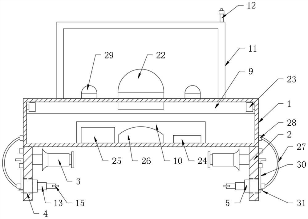
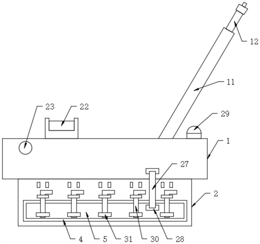
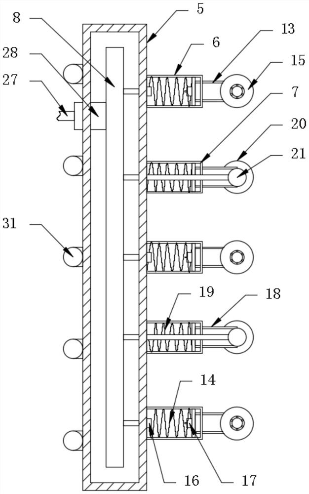
[0028] see Figure 1-5 , the present invention provides a technical solution: a device for continuous scanning and detection of railways, comprising a square main body 1 , a connecting plate 2 is fixed on both sides of the bottom end of the main body 1 , and the connecting plate 2 is close to an inner part of the main body 1 A roller 3 is installed on the side through the pillar, and the roller 3 is movably arranged under the main body 1. A placement slot 4 is opened on the bottom end of the surface of the connecting plate 2, and a movable plate 5 is movably installed inside the placement slot 4, and the movable plate 5 is close to the roller 3. A radian detection mechanism 6 is provided on one side, a mileage recording mechanism 7 is provided on the side of the mobile board 5 between the radian detection mechanisms 6, a circuit board 8 is installed inside the mobile board 5, a detection mechanism 9 is provided on the outer surface of the main body 1, and the interior of the main body 1 is provided with a detection mechanism 9. A processing mechanism 10 is installed, and a push rod 11 is provided at the outer top end of the main body 1 , and a data line 12 is installed inside the push rod 11 .
[0029] The arc detection mechanism 6 includes a first telescopic rod 13, a first spring 14, a first moving wheel 15, an infrared receiver 16, and an infrared transmitter 17. The first telescopic rods 13 are evenly arranged on the side of the moving plate 5, and the first spring 14 The first moving wheel 15 is disposed on the end of the first telescopic rod 13 away from the moving plate 5 through the bearing, and the infrared receiver 16 is disposed on the end of the first telescopic rod 13 close to the moving plate 5. The infrared transmitter 17 is disposed on the inner end of the first telescopic rod 13 close to the first moving wheel 15 , and the infrared receiver 16 is connected to the circuit board 8 through wires.
[0030] The mileage recording mechanism 7 includes a second telescopic rod 18, a second spring 19, a second moving wheel 20, and an encoder 21. The second telescopic rods 18 are evenly arranged on the side of the moving plate 5, and the second spring 19 is disposed on the second telescopic rod. 18 inner side wall, the second moving wheel 20 is arranged on the side of the second telescopic rod 18 away from the bottom end of the moving plate 5 through a bearing, and an encoder 21 is installed on the top of the second telescopic rod 18 close to the second moving wheel 20. The encoder The input end of 21 is connected to the second roller 3, and the encoder 21 is connected to the circuit board 8 through wires.
[0031] The detection mechanism 9 includes a first infrared radar 22 and a second infrared radar 23 . The first infrared radar 22 is disposed on the top of the main body 1 , and the second infrared radar 23 is inlaid and disposed on both sides of the main body 1 .
[0032] The processing mechanism 10 includes a central processing unit 24, a battery 25, and an electronic level 26. The central processing unit 24, the battery 25, and the electronic level 26 are evenly distributed inside the main body 1. The battery 25 is electrically connected to the central processing unit 24. The central processing unit 24 It is connected to the infrared receiver 16 , the encoder 21 , the first infrared radar 22 , the second infrared radar 23 , and the electronic level 26 .
[0033] There are connecting wires 27 on both sides of the main body 1. The two ends of the connecting wires 27 are fixedly provided with plugs 28. One end of the plug 28 is arranged on the surface of the opening moving plate 5 to be connected to the circuit board 8, and the other end of the plug 28 is arranged on the opening. The side surface of the main body 1 is connected to the central processing unit 24 .
[0034] A warning light 29 is provided on the side of the main body 1 near the top end of the push rod 11 , and the warning light 29 is connected to the central processing unit 24 .
[0035] A bolt 30 is installed on the top of the side of the connecting plate 2 away from the roller 3 by bolts, and a fixing ring 31 is arranged on the side of the side of the moving plate 5 away from the arc detection mechanism 6 .
[0036] One end of the data line 12 is connected to the central processing unit 24 , and the end of the data line 12 away from the central processing unit is disposed outside the push rod 11 .
[0037]Working principle: By placing the main body 1 on the track, the roller 3 is in contact with the track, and the push rod 11 is pushed to drive the main body 1 to move forward. The side of the connecting plate 2 is provided with a placement slot 4, so that the moving plate 5 drives the arc detection mechanism 6 and the mileage. The recording mechanism 7 contacts the side of the track, and passes through the fixed ring 31 through the latch 30, so that the moving plate 5 is arranged on the surface of the connecting plate 2, and the central processing unit 24 sends a signal to the battery 25, and sends a signal to the infrared transmitter 17 and the infrared receiver 16. , the encoder 21, the first infrared radar 22, the second infrared radar 23, and the electronic level 26 are powered, and the circuit board 8 is connected to the processing mechanism 10 through the plug 28 of the connecting wire 27, and the arc detection mechanism 6 is connected to the mileage recorder. The data of the mechanism 7 is transmitted to the central processing unit 24, and the first telescopic rod 13 is driven by the first spring 14 to perform telescopic movement, so that the first moving wheel 15 is in close contact with the track, and the infrared transmitter 17 sends out the infrared receiver 16. The light source measures the distance. By sending the three-stage signal of the radian detection mechanism 6 to the central processing unit 24, it is compared and observed whether the track has radians, and the radian of the track is recorded in time, and the second telescopic rod 18 can be driven by the second spring 19. The telescopic movement makes the second moving wheel 20 closely contact the track, and when the main body 1 is pushed to move, the second moving wheel 20 is driven to rotate, so that the encoder 21 rotates accordingly, and the pulse number of the encoder 21 is transmitted to the central processing unit 24 for calculation After the mileage of the machine movement, the second infrared radar 23 scans both sides of the track to transmit the data to the central processing unit 24, and the first infrared radar 22 scans the top of the track to transmit the data to the central processing unit 24. When the track turns, the central processing unit 24 calculates the data detected by the radian detection mechanism 6 and the tilt radian of the electronic level 26 to obtain whether the track has a super-high inclination angle, which is detected by the first infrared radar 22 and the second infrared radar 23. The distance between the outside of the track and the track is calculated by the central processing unit 24 whether the train is in contact with it when running. The height of the catenary can also be measured by the first infrared radar 22, and the pulse is transmitted to the central processing unit through the encoder 21. The device 24 calculates the mileage to obtain the span and pull-out value of the catenary, and connects the worker's mobile phone through the data cable 12. When there is an unqualified place, the alarm light 29 is first driven to give an alarm, and then the incorrect data is transmitted to the mobile phone. on the track, so that workers know what is wrong with the track and mark it on the track in time.
[0038] It should be noted that, in this document, relational terms such as first and second are used only to distinguish one entity or operation from another entity or operation, and do not necessarily require or imply any relationship between these entities or operations. any such actual relationship or sequence exists. Moreover, the terms "comprising", "comprising" or any other variation thereof are intended to encompass a non-exclusive inclusion such that a process, method, article or device that includes a list of elements includes not only those elements, but also includes not explicitly listed or other elements inherent to such a process, method, article or apparatus.
[0039] Although embodiments of the present invention have been shown and described, it will be understood by those skilled in the art that various changes, modifications, and substitutions can be made in these embodiments without departing from the principle and spirit of the invention and modifications, the scope of the present invention is defined by the appended claims and their equivalents.