
Train Control Method and System

a technology of train control and train tr, applied in the direction of brake systems, process and machine control, instruments, etc., can solve the problems of inability to stop the train tr, and inability of the operator of the train tr1/b> to become complacent, etc., to overcome drawbacks and deficiencies, and enhance the safety of the train traveling

Active Publication Date: 2010-03-11
WESTINGHOUSE AIR BRAKE TECH CORP
View PDF22 Cites 38 Cited by
  • Summary
  • Abstract
  • Description
  • Claims
  • Application Information

AI Technical Summary

Benefits of technology

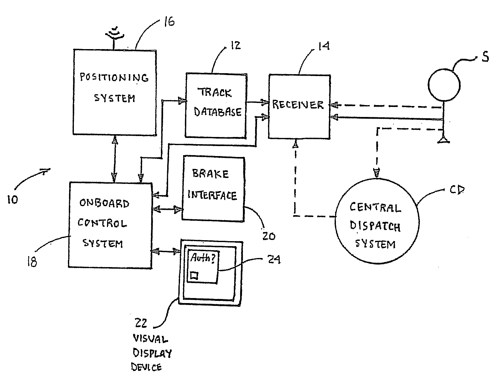
[0020]It is, therefore, an object of the present invention to provide a method and system for controlling a train that overcomes the drawbacks and deficiencies in the art of train control systems and the like. It is another object of the present invention to provide a method and system for controlling trains for predictively enforcing a stop for a train traveling in a track network and based upon signal aspect information. It is a further object of the present invention to provide a method and system for controlling trains that enhances the safety of trains traveling in a track network by enforcing or braking trains in certain situations. It is yet another object of the present invention to provide a method and system for controlling trains that protects against the train operator incorrectly assuming or guessing the signal aspect of an upcoming signal.

Problems solved by technology

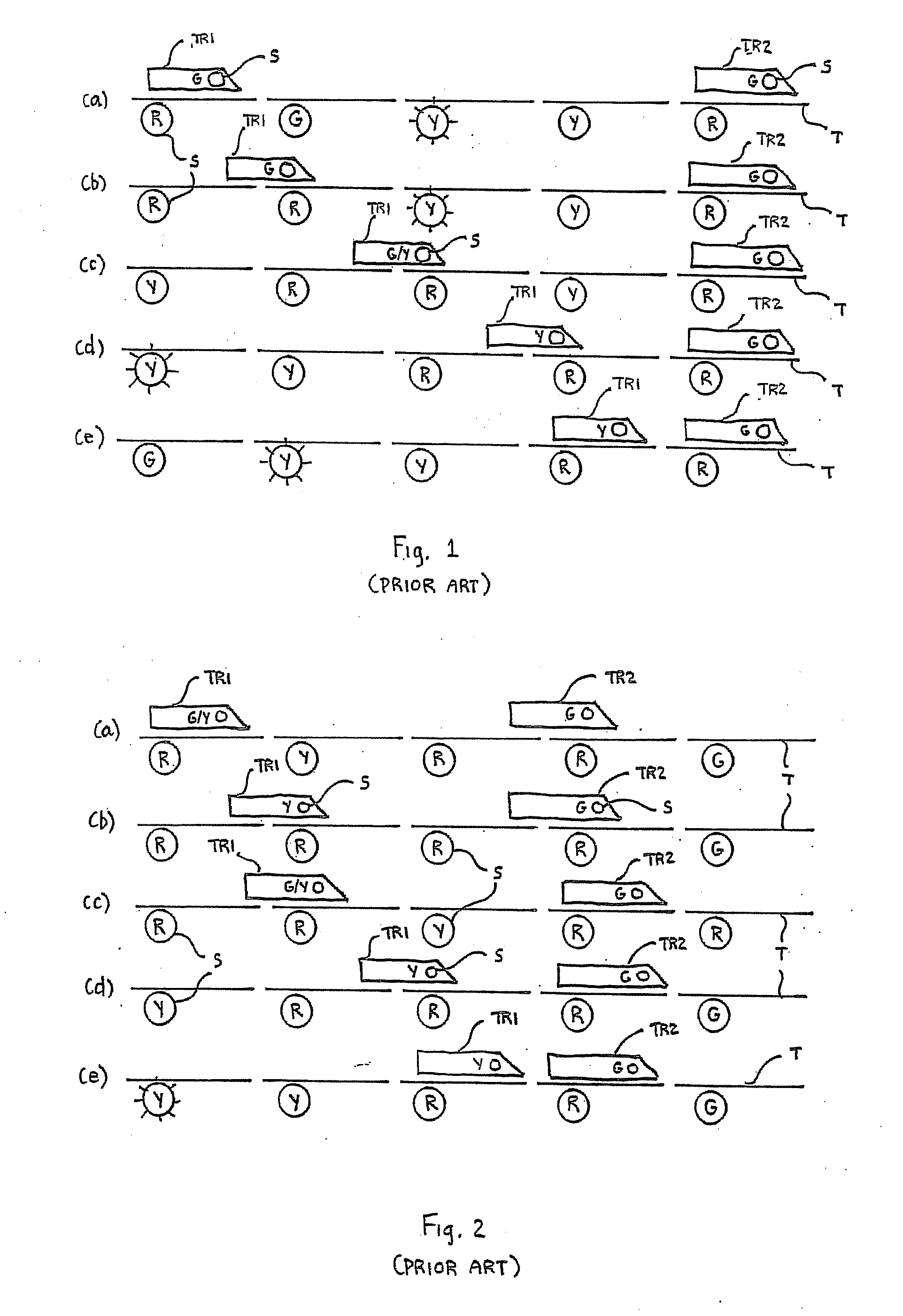
When the operator is lulled into a lower state of vigilance, he or she may not be operating the train in an appropriate manner to comply with the next, upcoming wayside signal aspect, e.g., “stop and proceed.” Therefore, due to this diminished state of vigilance, accidents or collisions may occur between trains (or other similar noncompliance issues may arise with respect to the next, upcoming signal).
Further, it is this sequence of events that may cause the operator of the train TR1 to become complacent.
However, and as illustrated in FIG. 2(e), and due to the stoppage of train TR2, train TR1 is now approaching a wayside signal S indicating “stop and proceed,” which requires that the train TR1 stop before any part of the train TR1 or engine passes the signal S, and then to proceed at restricted speed to the next signal S. However, the crew or operator may not be prepared to stop the train TR1 before passing this next, upcoming wayside signal S, since they are expecting the train TR1 cab signal indication to upgrade to “advance approach.” Not being able to stop in time, train TR1 will collide with train TR2.
These prior art systems and methods exhibit various drawbacks and deficiencies.

Method used


Image

  • Train Control Method and System
  • Train Control Method and System
  • Train Control Method and System

Examples


Embodiment Construction

[0029]It is to be understood that the invention may assume various alternative variations and step sequences, except where expressly specified to the contrary. It is also to be understood that the specific devices and processes illustrated in the attached drawings, and described in the following specification, are simply exemplary embodiments of the invention.

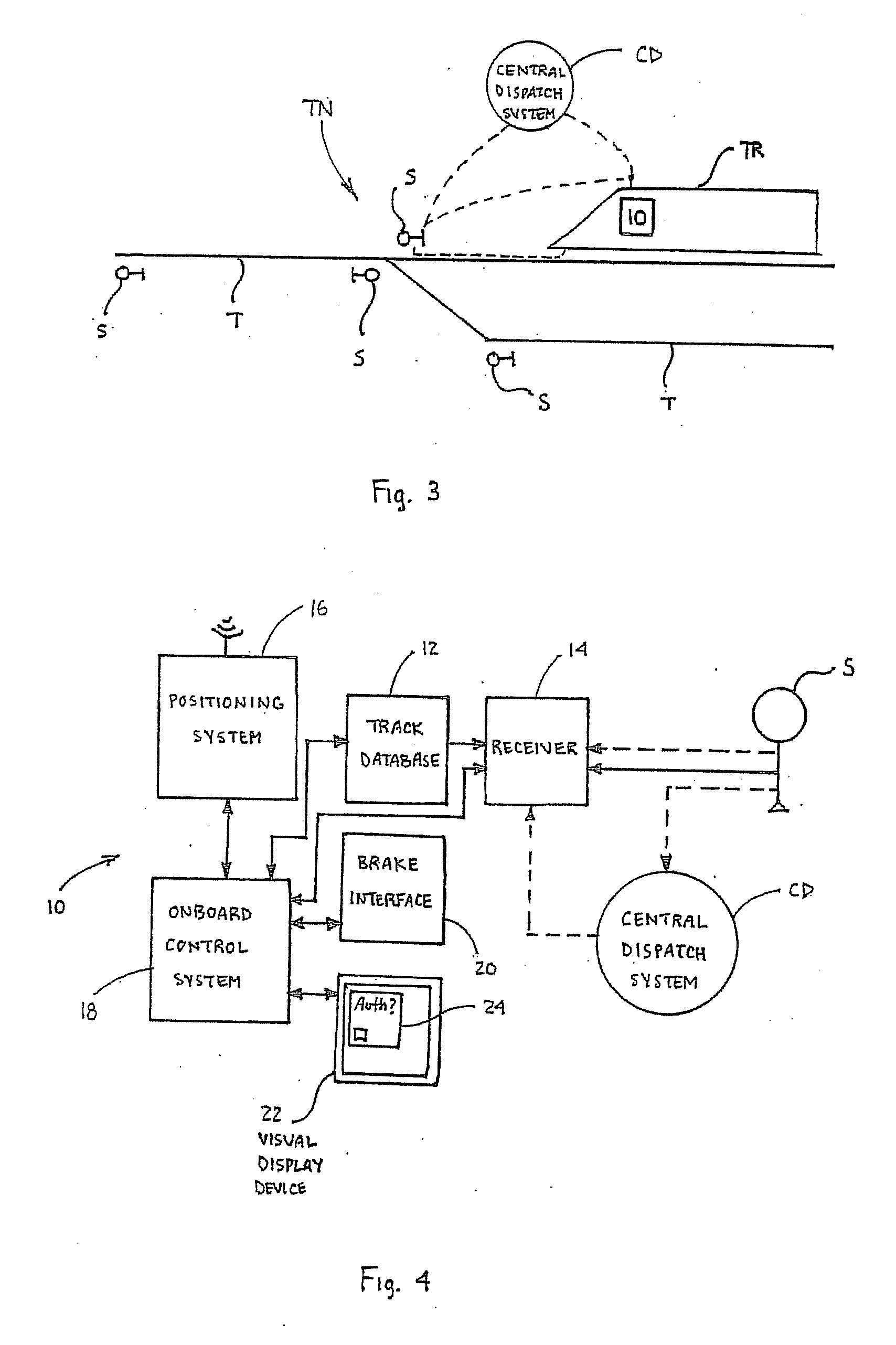
[0030]According to the present invention, provided is a method and system 10 for controlling at least one train TR traveling in a track network TN. The track network TN includes or is made up of multiple interconnected tracks T, and wayside signals S are associated with specific portions, e.g., blocks, of track T. For example, such portions of the track T are usually referred to as blocks, sections or circuits, and the associated signal S is positioned at the beginning of the block and provides information, aspects or indications related thereto.

[0031]It should be noted that the term “aspect” when used in connection with “signa...


PUM


Abstract

A train control system for controlling trains traveling in a track network including tracks with signals associated therewith. The system includes an on-board track database, a positioning system and an on-board control system. The on-board control system receives position data and automatically brakes the train prior to encountering an upcoming signal based upon specified data points. The train is not automatically braked if certain conditions are met. A method for controlling a train traveling in a track network is also disclosed.

Description

BACKGROUND OF THE INVENTION[0001]1. Field of the Invention[0002]The present invention relates generally to methods, systems and apparatus for controlling trains traveling in a track network made up of multiple tracks with signals associated with portions of the track and, in particular, to a system and method of controlling a train by predictively enforcing signal aspects as the train is moving through the track network.[0003]2. Description of Related Art[0004]As is known in the art, train control systems are used for monitoring, tracking and operating trains traversing tracks throughout a track network. In order to make appropriate train control decisions regarding how the train should be operated, whether manually, automatically or semi-automatically, important information and data must be obtained. In addition, and in order to provide for safe traffic control and avoid accidents or collisions, signals are provided throughout the track network, and each signal is typically associa...

Claims


Application Information

Patent Timeline
IPC IPC(8): G06F19/00
CPCB61L3/221B61L25/025B61L23/18B61L15/0072
Inventor KNOTT, JEFFREY G.GRAHAM, STEVE R.GRIMM, ANN K.MOORE, JAMES H.WILSON, M. FRANKKERNWEIN, JEFFREY D.
Owner WESTINGHOUSE AIR BRAKE TECH CORP
Learn More