
A special conductive rotary head for electroplating equipment

A technology of electroplating equipment and rotary head, which is applied in the direction of current conduction devices, electrolytic components, electrolytic processes, etc., and can solve problems such as the reduction of the contact surface between the electroplating brush and the metal to be plated, the slowing down of the anion transmission speed of the electroplating brush, etc., and achieve faster The effect of blowing and dripping to increase the diffusion area

Active Publication Date: 2021-11-05
河南泰鑫纳米科技有限公司
View PDF0 Cites 0 Cited by
  • Summary
  • Abstract
  • Description
  • Claims
  • Application Information

AI Technical Summary

Problems solved by technology

[0002] Electroplating uses electrolysis to attach a layer of metal film to the outer wall of the metal material to improve wear resistance and corrosion resistance. Metal plating forms the cathode, and the plating metal in the electroplating solution is reduced on the surface of the metal to be plated to form a coating. In order to make the metal to be plated have uniform anions, the conductive rotary head is equipped with an electroplating brush, which rotates around the outer wall of the metal for one revolution to transmit anions; In the prior art, when the conductive turret is used to transmit anions, when the weight of the electroplated metal is heavy, the metal is quickly inserted into the electroplating solution, and the electroplating solution is splashed upward by the impact force of the metal, and the distance between the conductive turret and the electroplated metal When it is close, the splashed electroplating solution adheres to the outer wall of the electroplating brush, and stays on the outer wall of the electroplating brush for a long time and is easily reduced by anions to form a coating, resulting in the reduction of the contact surface between the electroplating brush and the metal to be plated, resulting in the reduction of the anion transmission speed of the electroplating brush slow

Method used


Image

  • A special conductive rotary head for electroplating equipment
  • A special conductive rotary head for electroplating equipment
  • A special conductive rotary head for electroplating equipment

Examples


Embodiment 1

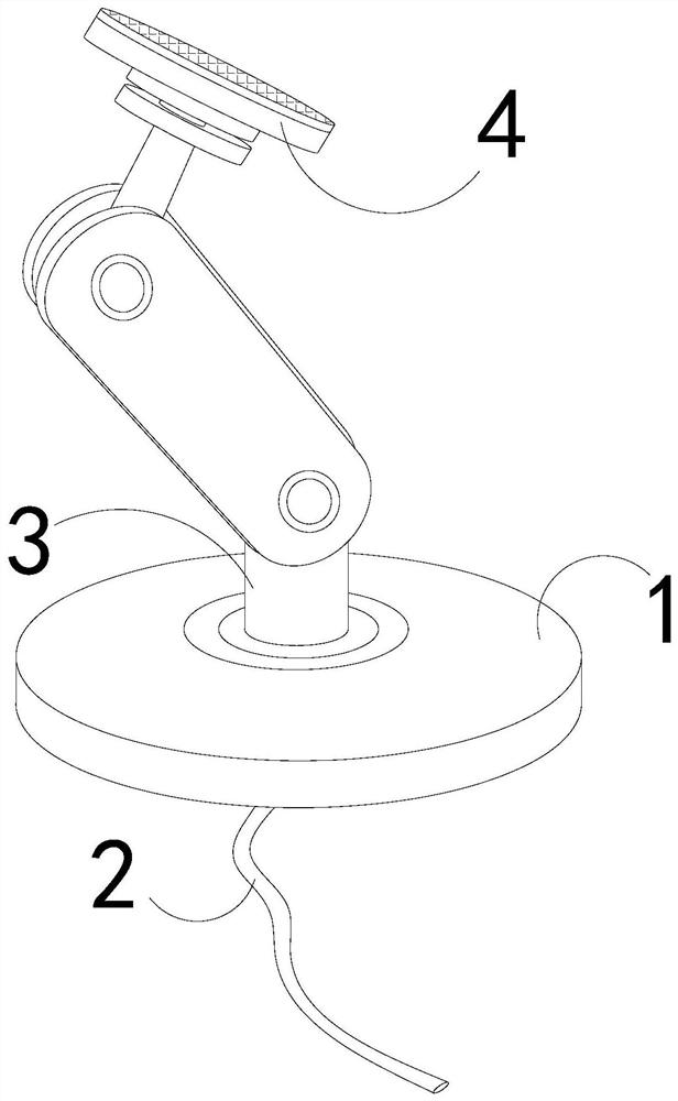
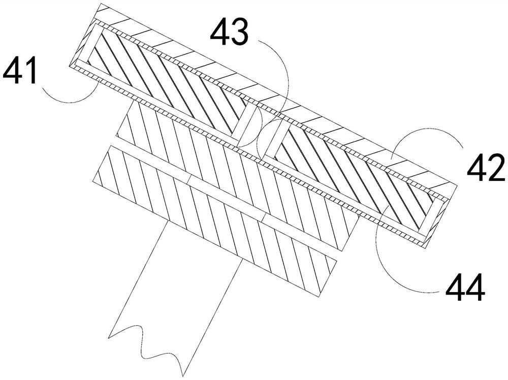
[0027] as attached figure 1 to attach Figure 5 Shown:

[0028] The invention provides a special conductive turret for electroplating equipment, the structure of which includes a base 1, a wire 2, a bearing 3, and a conductive mechanism 4. The wire 2 is installed at the center of the bottom of the base 1, and the bearing 3 is vertically installed on the base 1. At the top, the conductive mechanism 4 is movably matched with the top of the bearing 3 .

[0029] The conductive mechanism 4 is provided with a support 41, an electroplating brush 42, a push block 43, and a vibration device 44. The electroplating brush 42 is installed on the upper surface of the support 41, and the vibration device 44 is located inside the support 41. The push block 43 Sandwiched between vibration devices 44 .

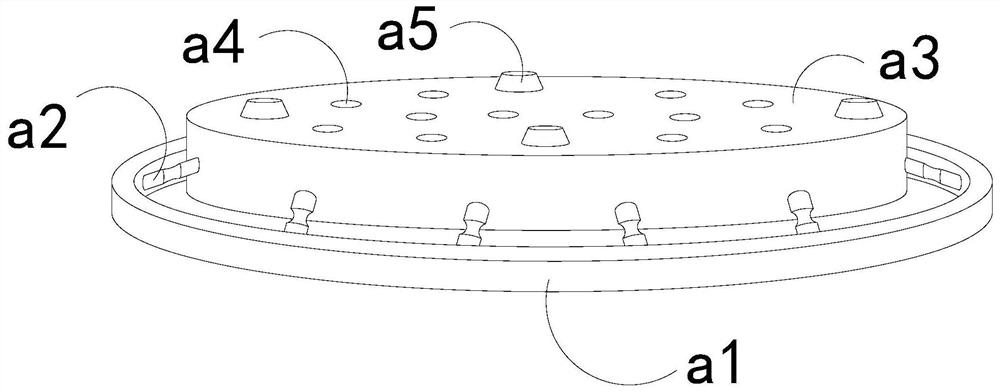
[0030] Wherein, the vibration device 44 is provided with a support ring a1, a telescopic rod a2, a built-in plate a3, an opening a4, and a bump a5, the support ring a1 is located outside the...

Embodiment 2

[0036] as attached Figure 6 to attach Figure 8 Shown:

[0037]Wherein, the opening a4 is provided with a limit bar r1, a dispersion block r2, a scraper r3, and an exhaust port r4, the limit bar r1 is arranged on both sides of the opening a4, and the dispersion block r2 is sandwiched between the limit bar r1 In between, the scraper r3 is embedded at both ends of the dispersion block r2, and the exhaust port r4 runs through the upper and lower surfaces of the dispersion block r2. There are three exhaust ports r4, and the diameter gradually decreases from top to bottom. It is beneficial to increase the gas diffusion area at the top of the exhaust port r4, and the side end of the scraper blade r3 is pointed, which is beneficial to accelerate the dropping of the electroplating solution on the inner wall of the opening a4.

[0038] Wherein, the exhaust port r4 is provided with a support frame t1, a blocking plate t2, and a spring t3, the support frame t1 is located outside the e...


PUM


Abstract

The invention discloses a special conductive turret for electroplating equipment. The structure includes a base, a wire, a bearing, and a conductive mechanism. When the distance between the conductive turret and the electroplated metal is close, the splashed electroplating solution adheres to the outer wall of the electroplating brush, and the electroplating brush is pushed and vibrated by the vibration device, and the electroplating solution on the outer wall of the electroplating brush is subjected to shaking force to drip, reducing the long-term maintenance of the electroplating solution. Residing on the outer wall of the electroplating brush and being reduced by anions to form a plating layer, increasing the contact surface between the electroplating brush and the metal to be plated, speeding up the transmission of anions to the metal by the electroplating brush, when the vibration force received by the electroplating brush is small, the flow speed of the electroplating solution is slow, Diffusion of the discharged gas through the dispersing block inside the opening is beneficial to increase the diffusion area of ​​the gas and accelerate the blowing and dripping of the electroplating solution on the outer wall of the electroplating brush by the gas.

Description

technical field [0001] The invention belongs to the field of electroplating, and more specifically relates to a special conductive rotary head for electroplating equipment. Background technique [0002] Electroplating uses electrolysis to attach a layer of metal film to the outer wall of the metal material to improve wear resistance and corrosion resistance. Metal plating forms a cathode, and the plating metal in the electroplating solution is reduced on the surface of the metal to be plated to form a coating. In order to make the metal to be plated have uniform anions, the conductive rotary head is equipped with an electroplating brush, which rotates around the outer wall of the metal for one revolution to transmit anions; In the prior art, when the conductive turret is used to transmit anions, when the weight of the electroplated metal is heavy, the metal is quickly inserted into the electroplating solution, and the electroplating solution is splashed upward by the impact ...

Claims


Application Information

Patent Timeline
Patent Type & Authority Patents(China)
IPC IPC(8): C25D17/00C25D5/06
CPCC25D5/06C25D17/007
Inventor 郑志阳
Owner 河南泰鑫纳米科技有限公司
Learn More