Foldable drying machine

A dryer and folding drying technology, applied in the field of dryers, can solve the problems of collapse of folding brackets, failure to function, inconvenience of normal use, etc., and achieve the effect of not being easy to collapse

Pending Publication Date: 2021-02-23
BEAR ELECTRICAL APPLIANCE CO LTD +1
View PDF1 Cites 2 Cited by
  • Summary
  • Abstract
  • Description
  • Claims
  • Application Information

AI Technical Summary

Problems solved by technology

The disadvantage of this hinge method is that it is necessary to disassemble the middle shelf to fold the folding bracket, which is cumbersome and inconvenient to operate; the side panels of the hinge only serve to prevent the folding bracket from rotating and folding outward, and do not play a stable folding role. When the bracket is unfolded, if there is no intermediate shelf, a little external force will easily cause the folding bracket to rotate inward and collapse, which is not convenient for normal use

Method used


Image

  • Foldable drying machine
  • Foldable drying machine
  • Foldable drying machine

Examples


Embodiment 1

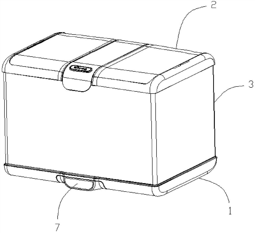
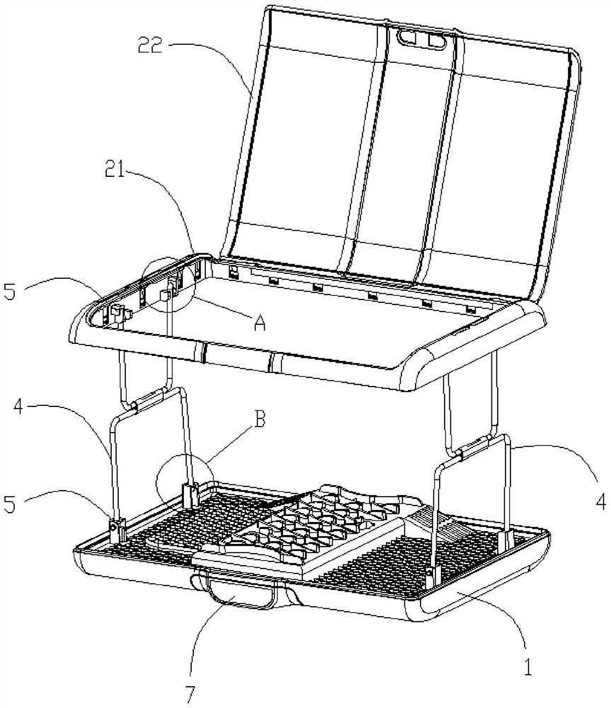
[0049] refer to Figure 1 to Figure 8, the invention discloses a dryer, comprising a base assembly 1, an upper cover assembly 2, a drying cover 3 and a support assembly. The base assembly 1 is provided with a host assembly 7 for providing hot air. Preferably, the host assembly 7 is detachably arranged on the base assembly 1; the support assembly is connected to the base assembly 1 and the upper cover The upper cover assembly 2 is stretched between the components 2; the drying cover 3 is connected between the base assembly 1 and the upper cover assembly 2 to form a drying chamber for accommodating clothes.

[0050] Wherein, the support assembly is at least two sets of hinge assemblies 4, the two ends of the hinge assembly 4 are respectively hinged on the base assembly 1 and the upper cover assembly 2, and the upper cover assembly can be moved by the hinge assembly 4 2 is supported so that the drying cover 3 forms a drying chamber for accommodating clothes between the base asse...

Embodiment 2

[0068] refer to Figure 9 to Figure 15 The difference between this embodiment and Embodiment 1 is that the dryer disclosed in this embodiment specifically discloses a specific structure in which the cloth cover 31 is detachably connected between the base assembly 1 and the upper cover assembly 2 .

[0069] The dryer provided in this embodiment includes the base assembly 1 , the upper cover assembly 2 , the cloth cover 31 and the supporting assembly as described in the first embodiment.

[0070] In this embodiment, the upper and lower ends of the cloth cover 31 are provided with buckle edges 32, the base assembly 1 and the upper cover assembly 2 are both provided with a card slot 6, and the card slot 6 is provided with a The buckle portion 61 is snap fit with the buckle edge 32 ; through the relative fit between the buckle edge 32 and the buckle portion 61 , the cloth cover 31 is detachably connected between the base component 1 and the upper cover component 2 .

[0071] Wher...

Embodiment 3

[0084] refer to Figure 16 to Figure 22 The difference between this embodiment and Embodiment 1 or 2 is that the dryer disclosed in this embodiment specifically discloses a detachable main body structure in which the main body assembly 7 is detachably installed on the base assembly 1 .

[0085] In this embodiment, the detachable host structure includes a dryer main body and the host assembly 1 , and the dryer main body includes a bottom case. Wherein, the main body of the dryer includes the upper cover assembly 2, the base assembly 1, the support assembly and the drying cover 3 as described in Embodiment 1 or 2, and the bottom shell of the main body of the dryer is the base assembly 1 The bottom shell 11.

[0086] In this embodiment, the bottom of the bottom case 11 is provided with an installation cavity 111 opening downward, and the side wall of the installation cavity 111 is provided with a slider 112; the host assembly 7 includes a host housing 71, and the host housing T...


PUM


Abstract

The invention discloses a foldable drying machine which comprises a base assembly, an upper cover assembly, a clothes drying cover and at least two hinge assemblies, wherein a main machine assembly isarranged on the base assembly, the clothes drying cover is connected between the base assembly and the upper cover assembly, each hinge assembly comprises two hinges which are rotationally connectedwith each other, the upper cover assembly and the base assembly are provided with hinge seats rotationally matched with the hinges, each hinge seat is provided with a first positioning groove, and when the hinge assemblies are unfolded, the two hinges are embedded and positioned in the first positioning grooves of the two hinge seats correspondingly. In the drying machine, the drying machine can be folded and unfolded through the hinge assemblies, the hinges in an unfolded state are positioned through the first positioning grooves of the hinge seats so as to stabilize the states of the hinge assemblies in the unfolded state, the hinge assemblies are not prone to collapsing, and when folding is needed, the hinges only need to be driven by external force to be disengaged from the first positioning grooves to release positioning, and thus folding operation can be achieved.

Description

technical field [0001] The invention relates to the technical field of dryers, in particular to a foldable dryer. Background technique [0002] As a machine for drying clothes, dryers have gradually become a necessity in people's lives. As a market segment, the folding portable dryer brings greater convenience to people. However, the unreasonable design of the folding structure of the existing foldable portable dryer results in difficulty in folding and often requires the cooperation of both hands. [0003] CN202010014944.X discloses a split-type foldable portable clothes dryer, the folding function of which is realized by a foldable support. The foldable support includes a plurality of sequentially connected support rods, and two adjacent support rods are hinged through hinges. The hinge is composed of two side plates, two poles are hinged with the same side plate, and the other side plate plays a positioning role for the unfolded folding bracket. The disadvantage of thi...

Claims


Application Information

Patent Timeline
Patent Type & Authority Applications(China)
IPC IPC(8): D06F58/14D06F58/20
CPCD06F58/14D06F58/20
Inventor 李一峰梁海权黎鉴池
Owner BEAR ELECTRICAL APPLIANCE CO LTD
Why Eureka
Try Eureka