Simple automatic laminating device on vibrating beam

A vibrating beam and automatic technology, which is applied in the processing of building materials, construction, building construction, etc., can solve the problems of cumbersome film covering operations, affecting the quality of film covering maintenance, troublesome installation and disassembly of bolt connections, etc.

Pending Publication Date: 2021-02-23
CHINA CONSTR SEVENTH ENG DIVISION CORP LTD
View PDF0 Cites 4 Cited by
  • Summary
  • Abstract
  • Description
  • Claims
  • Application Information

AI Technical Summary

Problems solved by technology

[0004] 1. Most of the existing concrete film covering devices use artificial film covering, which is cumbersome to operate and consumes a lot of manpower and material resources. It cannot achieve a good surface closing effect, and it is difficult to overlap and smooth the films, which affects the film coverage. maintenance quality;
[0005] 2. Most of the existing concrete coating devices are fixed by welding or bolts. It is difficult to disassemble after welding and installation, which is not conducive to the transportation of the device. The installation and disassembly of bolt connection is too troublesome

Method used


Image

  • Simple automatic laminating device on vibrating beam
  • Simple automatic laminating device on vibrating beam
  • Simple automatic laminating device on vibrating beam

Examples


Embodiment Construction

[0023] The following will clearly and completely describe the technical solutions in the embodiments of the present invention with reference to the accompanying drawings in the embodiments of the present invention. Obviously, the described embodiments are only some, not all, embodiments of the present invention. Based on the embodiments of the present invention, all other embodiments obtained by persons of ordinary skill in the art without making creative efforts belong to the protection scope of the present invention.

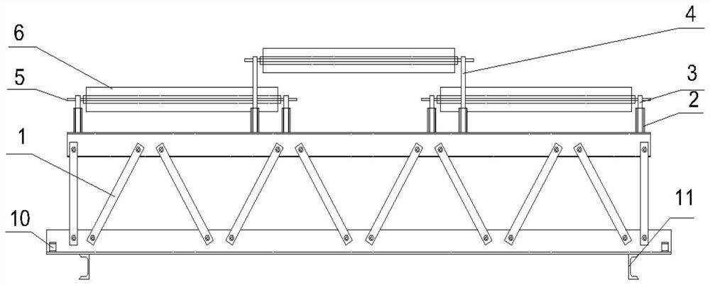
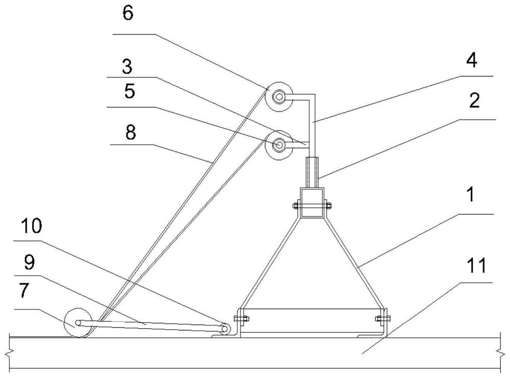
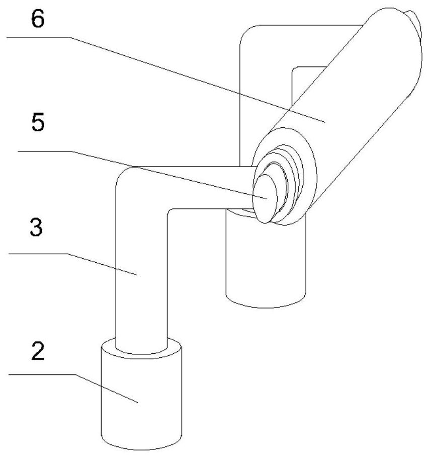
[0024] see Figure 1-4 , in this embodiment: a simple device for automatic coating on a vibrating beam, comprising a vibrating beam 1, a support base 2 is arranged on the upper end of the vibrating beam 1, a low support 3 is provided on the upper end of the support base 2, and a low support 3- The side is provided with a high bracket 4, the inside of the low bracket 3 and the high bracket 4 is provided with a rotating shaft 5, the outer side of the rotating sh...


PUM


Abstract

The invention discloses a simple automatic laminating device on a vibrating beam. The simple automatic laminating device comprises the vibrating beam, a support base is arranged at the upper end of the vibrating beam, a low support is arranged at the upper end of the support base, a high support is arranged on one side of the low support, a rotating shaft is arranged in the low support and the high support in a penetrating mode, a film roll is arranged on the outer side of the rotating shaft in a penetrating mode, a laminating rolling bar is arranged on the side, close to the film roll, of thevibrating beam, a film is arranged between the film roll and the laminating rolling bar, and a rolling bar traction rod is arranged on the side, close to the vibrating beam, of the laminating rollingbar. According to the device, by arranging the low support and the high support, film lap joint can be facilitated, and the maintenance quality of film covering is ensured. By arranging the laminating rolling bar, the film can be evenly, flatly and tightly attached to the surface of concrete, and the frequency of manual rework is reduced. By arranging the support base, the low support and the high support can be mounted and dismounted more conveniently.

Description

technical field [0001] The invention relates to the technical field of film covering equipment, in particular to a simple device for automatic film covering on a vibrating beam. Background technique [0002] At present, concrete projects using vibrating beams are generally characterized by thin concrete pouring thickness and large construction work surface. The width of the film purchased on the market cannot cover the surface of the cast-in-place concrete at one time, which requires additional workers. Cover the concrete surface with a film; when manually covering the concrete surface with a film, it is necessary to close the surface again to eliminate the footprints left, which is cumbersome to operate, labor-intensive and time-consuming, increases costs and cannot achieve a good surface closing effect , Especially when working in high temperature weather in summer, the water on the concrete surface loses quickly. If the film cannot be covered in time to preserve the water...

Claims


Application Information

Patent Timeline
Patent Type & Authority Applications(China)
IPC IPC(8): E04G21/24E04G21/06
CPCE04G21/066E04G21/246
Inventor 陶必存许旋黄诗东万超陈聪
Owner CHINA CONSTR SEVENTH ENG DIVISION CORP LTD
Why Eureka
Try Eureka