Check patentability & draft patents in minutes with Patsnap Eureka AI!

High-voltage power grid protection equipment

A technology of high-voltage power grid and protection equipment, applied in the field of power grid, can solve problems such as power grid circuit cut off

Inactive Publication Date: 2021-02-23
高丽娜
View PDF0 Cites 1 Cited by
  • Summary
  • Abstract
  • Description
  • Claims
  • Application Information

AI Technical Summary

Problems solved by technology

[0003] Because the high-voltage power grid circuit breaker needs to be exposed to the outside for a long time, there will be rainwater at the connection between the power breaker and the power connection block after a rainy day. , it will bring up an arc-shaped rainwater. We all know that water is conductive, so that the arc-shaped rainwater brought up will also conduct current, which will cause the high-voltage power grid circuit breaker to be unable to cut off the power grid circuit instantly.

Method used


Image

  • High-voltage power grid protection equipment
  • High-voltage power grid protection equipment
  • High-voltage power grid protection equipment

Examples


Embodiment 1

[0026] For example figure 1 -example Figure 5 Shown:

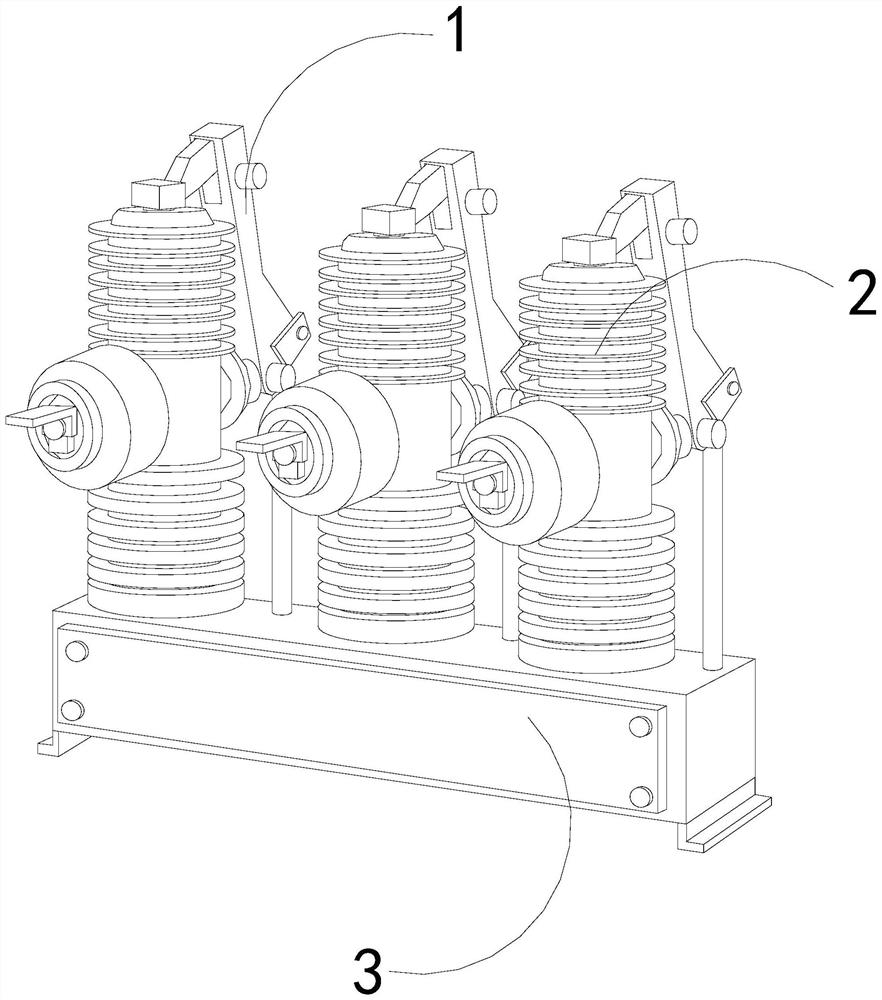
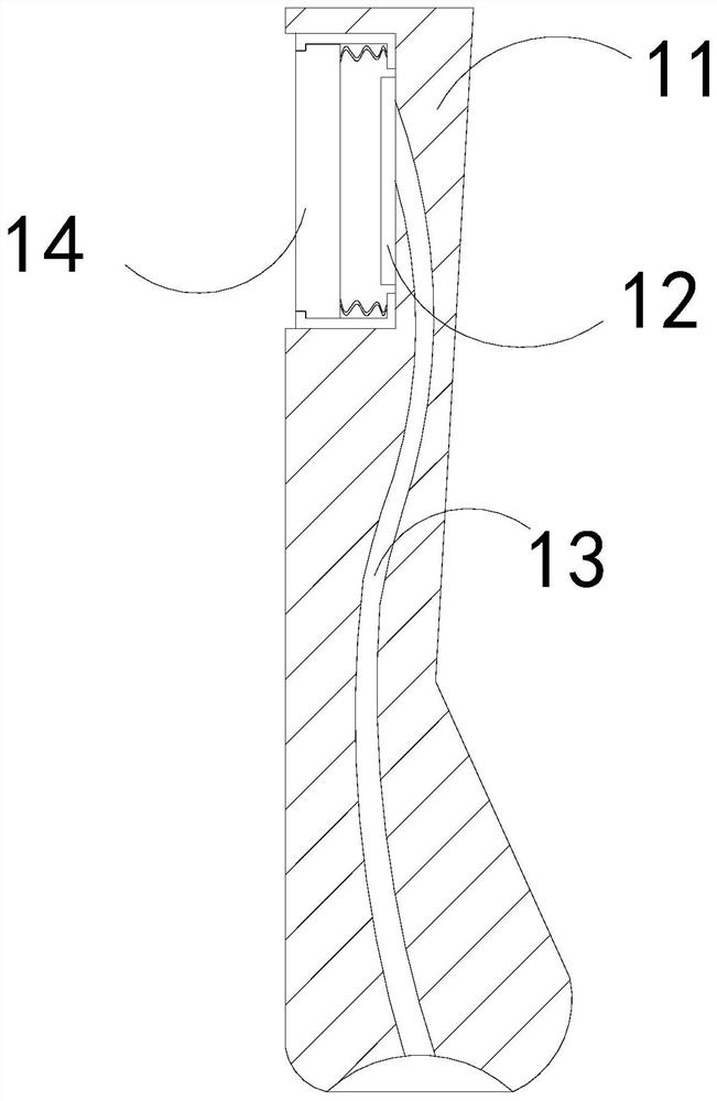
[0027] The invention provides a high-voltage power grid protection device, the structure of which includes a power breaker 1, a power connection post 2, and a base 3. The power connection post 2 is embedded and fixed on the upper surface of the base 3. 3 Hinge connection; the power breaker 1 includes a plate body 11, a power connection plate 12, a conductive wire 13, and a contraction plate 14. The power connection plate 12 is embedded and fixed on the right side of the inner wall of the plate body 11, and the conductive wire 13 runs through the inner position of the plate body 11 , and the shrinkable plate 14 is movably engaged with the plate body 11 .

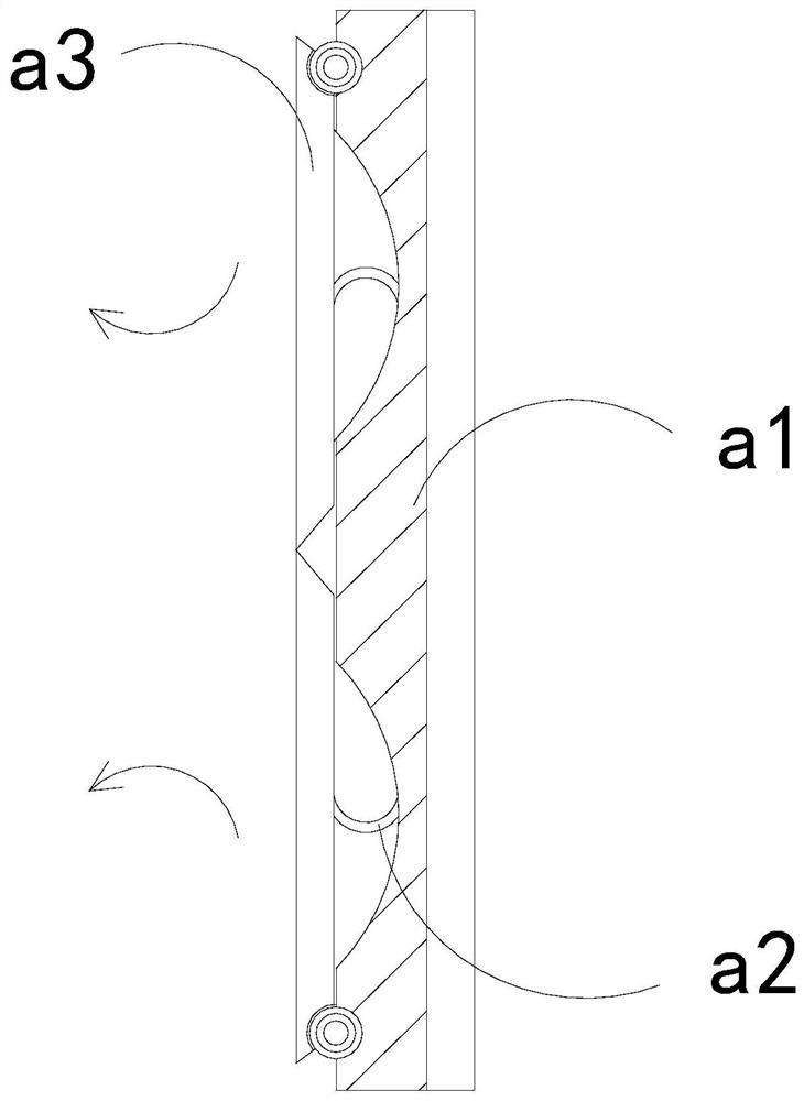
[0028] Wherein, the contraction plate 14 includes a plate a1, an elastic piece a2, and a swing plate a3, the elastic plate a2 is installed between the plate a1 and the inner side of the swing plate a3, and the swing plate a3 is hinged to the left side of the plate a1 ...

Embodiment 2

[0034] For example Image 6 -example Figure 8 Shown:

[0035] Wherein, the sump b4 includes a bottom plate b41, a pull-back piece b42, an extension block b43, and an inner connection plate b44, and the pull-back piece b42 is installed between the extension block b43 and the bottom plate b41. The protruding block b43 is in clearance fit with the inner connecting plate b44, and the said inner connecting plate b44 and the bottom plate b41 are of an integrated structure. The distribution on the plate b44 is symmetrical, and the stretching force generated by the outward extension of the mechanism can make the extension block b43 extend outward along the inner connecting plate b44 under the cooperation of the pull-back piece b42.

[0036] Wherein, the protruding block b43 includes a base plate c1, an engaging piece c2, and an expansion plate c3. The engagement piece c2 is installed between the expansion plate c3 and the base plate c1. The expansion plate c3 and the left side of t...


PUM


Abstract

The invention discloses high-voltage power grid protection equipment which structurally comprises a power-off brake, a power connection column and a base. The power connection column is fixedly embedded in the upper surface of the base, the power-off brake is hinged to the base, and when a power grid line is short-circuited, the power-off brake rapidly swings and is disconnected so that a contraction plate can rapidly extend forwards, and current transmission can be instantly cut off; and the contraction plate extends outwards to generate an inertia force, and the swing plate can swing outwards along the plate block so that rainwater on the surface of the swing plate can be ejected outwards through the swing plate, and a pull-back piece can extend outwards under the cooperation of the extension block through inertia force generated by outward extension of the contact plate; and through extrusion of dust in a water collecting tank to the position between the two, an expansion plate canbe expanded outwards along a bottoming plate, and therefore the expansion plate can scatter the dust in the water collecting tank.

Description

technical field [0001] The invention relates to the field of power grids, in particular to a high-voltage power grid protection device. Background technique [0002] The high-voltage power grid circuit breaker is mainly used for emergency disconnection of the high-voltage power grid. It is usually installed in the middle of the power grid circuit. When the power grid circuit is short-circuited, it can be disconnected in an emergency, so as to protect the power grid. Based on the above description, the inventors found that the existing high-voltage power grid protection equipment mainly has the following deficiencies, for example: [0003] Because the high-voltage power grid circuit breaker needs to be exposed to the outside for a long time, there will be rainwater at the connection between the power breaker and the power connection block after a rainy day. , an arc-shaped rainwater will be brought up. It is well known that water is conductive, so that the arc-shaped rainwat...

Claims


Application Information

Patent Timeline
Patent Type & Authority Applications(China)
IPC IPC(8): H02J3/00H02H7/26H01H9/04
CPCH01H9/04H02H7/26H02J3/00
Inventor 高丽娜
Owner 高丽娜
Features
  • R&D
  • Intellectual Property
  • Life Sciences
  • Materials
  • Tech Scout
  • Unparalleled Data Quality
  • Higher Quality Content
  • 60% Fewer Hallucinations
Learn More