[0022]In the following, the present invention will be further described in detail with reference to the drawings and embodiments. The same parts are indicated by the same reference numerals. It should be noted that the words "front", "rear", "left", "right", "upper" and "lower" used in the following description refer to the directions in the drawings, and the words "bottom" and "top" "Face", "inner" and "outer" respectively refer to directions toward or away from the geometric center of a particular component.
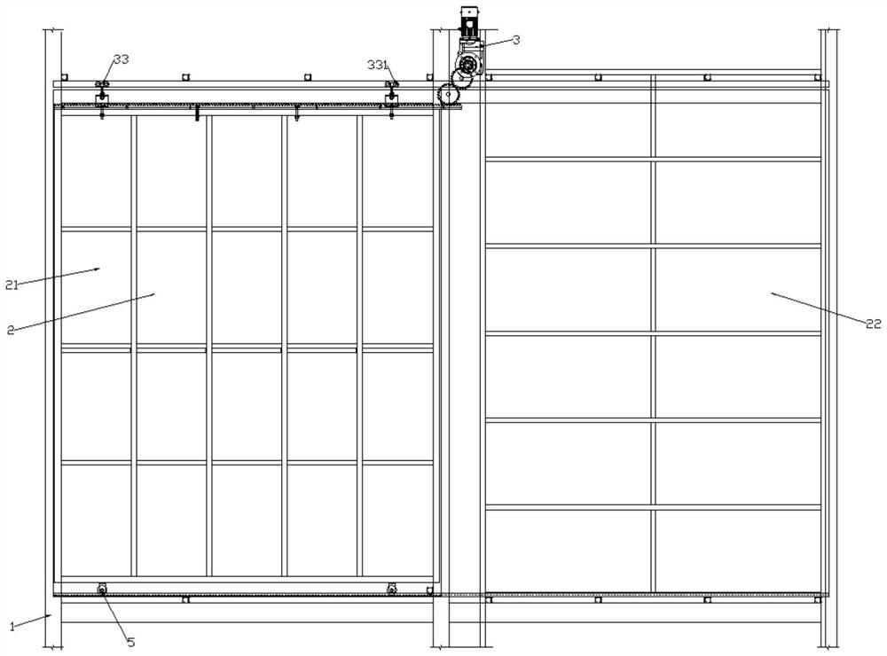
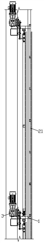
[0023]Refer toFigure 1 to Figure 5As shown, a mobile acoustic device of this embodiment includes a frame 1, which can be set on an indoor wall. When the wall of the interior is a glass wall, the frame 1 is provided with several groups of anti-sounds. Mechanism 2, which can be composed of multiple groups of anti-sound mechanisms 2 to form a wall surface. The anti-sound mechanism 2 includes a movable anti-sound plate 21, a fixed anti-sound plate 22 and a mobile assembly 3. The mobile assembly 3 includes a power part 31, a fixed part 32 and several The guide part 33 and the multiple guide parts 33 make the movement of the mobile anti-acoustic plate 21 more stable. The guide part 33 is used to restrict the moving direction of the moving anti-acoustic plate 21. The power part 31 passes through the fixed part 32 to reverse the movement. The sound board 21 moves along the direction defined by the guide portion 33, and the defined direction is the first direction or the second direction. The fixing portion 32 includes a fixing plate 321. By providing the fixing plate 321, the position where the rack 6 can be placed is increased. The number of fixable objects is also increased. The guide portion 33 includes an upper guide wheel set 331. An elastic portion 4 is arranged between the upper guide wheel set 331 and the fixing plate 321. The elastic portion 4 can be deformed and can change the upper guide wheel set 331. The distance between the upper guide wheel set 331 and the fixed plate 321 is fixedly connected to the fixed plate 321 through the elastic part 4, the elastic part 4 includes an elastic member 41, the fixed part 32 includes a connecting block 322, and the connecting block 322 is connected to the moving anti-acoustic plate 21 The elastic member 41 is fixedly connected to the connecting block 322 through the fixed plate 321. The elastic member 41 can be U-shaped steel. The opening direction of the U-shaped steel is perpendicular to the connection line between the fixed plate 321 and the upper guide wheel set 331, so that the U-shaped steel The steel plates on both sides are deformed, so that the U-shaped steel has a different tension on the fixed plate 321, and also a different tension on the upper guide wheel group 331, which can change the friction force of the upper guide wheel group 331, and fix the anti-sound plate 22 and A hidden space is formed between the frame 1, and the moving assembly 3 drives the mobile anti-sound board 21 to move in the first direction to make the mobile anti-sound board 21 enter the hidden space, so that the mobile anti-sound board 21 is blocked by the fixed anti-sound board 22, Change the light transmission area and range of the formed wall, thereby changing the illuminance of the entire room, and also changing the actual number of mobile anti-sound panels 21 used, changing the anti-sound effect, so that the indoor sound can produce different effects, move the component 3 The mobile anti-acoustic plate 21 is driven to move in the second direction to move the mobile anti-acoustic plate 21 out of the hidden space, and the first direction is deviated from the second direction. The first direction and the second direction may both be horizontal directions, which are divided into left and right movement.
[0024]Refer tofigure 1 withfigure 2 As shown, the distance moved by the mobile anti-acoustic plate 21 into the hidden space is the first distance, and the distance between every two adjacent fixed anti-acoustic plates 22 is less than or equal to the first distance, when the mobile anti-acoustic plate 21 is located in the hidden space. When in the space, the fixed anti-acoustic plate 22 covers the mobile anti-acoustic plate 21, so that after the mobile anti-acoustic plate 21 moves into the hidden space, the mobile anti-acoustic plate 21 does not work, and before moving, the mobile anti-acoustic plate 21 is located All appear at the position, the light intensity that can be changed by a single mobile anti-acoustic plate 21 increases, the distance that the mobile anti-acoustic plate 21 moves out of the hidden space is the second distance, and the first distance is equal to the second distance.
[0025]Refer tofigure 1 ,figure 2 withimage 3 As shown, the power unit 31 includes a motor 311 and a gear set 312. The motor 311 is fixedly connected to the frame 1, and a rack 6 is fixedly connected to the fixed plate 321. More stable, the motor 311 drives the rack 6 to move in the first direction or the second direction through the gear set 312. The gear set 312 includes a first gear 313, a second gear 314, and a third gear 315. The first gear 313 is fixedly connected to the output shaft of the motor 311, the first gear 313 is meshed with the second gear 314, and the third gear 315 is connected to the second gear. The gears 314 are meshed. The first gear 313, the second gear 314 and the third gear 315 are arranged so that the rotation direction of the output end of the motor 311 is the same as that of the third gear 315, which facilitates the setting of the program of the motor 311. The gears 315 are all rotatably connected to the frame 1, and the number of teeth of the first gear 313 is less than the number of teeth of the second gear 314, so that when the power of the first gear 313 is transmitted to the second gear 314, the speed of the second gear 314 is reduced, which can be controlled The rotation speed of the second gear 314 controls the moving speed of the moving anti-acoustic plate 21. The number of teeth of the second gear 314 is the same as the number of teeth of the third gear 315, and the modules of the first gear 313, the second gear 314, and the third gear 315 Similarly, the third gear 315 meshes with the rack 6.
[0026]Refer tofigure 1 ,figure 2 withFigure 5 As shown, the upper guide wheel group 331 includes a hanging rail 332, a guide block 333 and a number of upper guide wheels 334. The hanging rail 332 is fixedly connected to the frame 1, the upper guide wheel 334 is slidably connected in the hanging rail 332, and the upper guide wheel 334 Rotatingly connected with the guide block 333, the guide block 333 is fixedly connected with bolts, and the bolts are fixedly connected to the elastic member 41 by nuts. The positions of the bolts fixed on the elastic member 41 are different, that is, a threaded hole is opened on the U-shaped steel, and the bolt extends The different depths of the threaded holes change the tightening force of the bolt on the upper guide wheel 334, so that the pressing force between the upper guide wheel 334 and the hanging rail 332 is different, which can change the distance between the upper guide wheel 334 and the hanging rail 332. The friction force prevents the upper guide wheel 334 from separating from the hanging rail 332 during the sliding process in the hanging rail 332.
[0027]ReferenceFigure 5 As shown, the hanging rail 332 includes two grooves 335, the two grooves 335 are arranged oppositely, the upper guide wheels 334 are arranged in four, and the four upper guide wheels 334 are arranged so that the upper guide wheels 334 drive the moving sound counter 21 During the movement, it is more stable. Each groove 335 is slidably connected with two upper guide wheels 334. The arrangement of the grooves 335 makes the upper guide wheels 334 have restrictions on both sides, preventing the upper guide wheels 334 from being separated from the hanging rail 332.
[0028]Referencefigure 1 ,figure 2 withFigure 4 As shown, the guide portion 33 includes a lower guide wheel group 5, the lower guide wheel group 5 plays a role of supporting the moving anti-sound plate 21, the lower guide wheel group 5 is provided with two groups, which correspond to the upper guide wheel group 331 one by one, so that The movement of the mobile anti-acoustic plate 21 is more stable. The lower guide wheel set 5 includes a rail frame 51, which is fixedly connected to the frame body 1, and a lower guide wheel 52 is rotatably connected to the track frame 51, and the frame body 1 is fixedly connected to There is a guide rail 53 which is located below the lower guide wheel 52 and abuts against the lower guide wheel 52. The lower guide wheel 52 includes a roller groove 521, the guide rail 53 includes a limit end 531, the guide rail 53 can be set as an angle steel, the limit end 531 is a right-angle end of the angle steel, the limit end 531 is matched with the roller groove 521 and is embedded in the roller groove In 521, during the movement of the lower guide wheel 52, the moving direction will not deviate, and the moving anti-acoustic plate 21 will not shake, making the moving anti-acoustic plate 21 more stable.
[0029]Working principle: When moving the moving anti-acoustic plate 21, the motor 311 starts, the motor 311 rotates forward, driving the first gear 313 to rotate, the first gear 313 is reduced by the second gear 314, and the second gear 314 is passed through the third gear The transmission of 315 drives the rack 6 to move. The rack 6 drives the moving anti-sound plate 21 to move through the fixed plate 321. The moving anti-sound plate 21 moves in the first direction and enters the hidden space. It is located between the fixed anti-sound plate 22 and the frame 1. At the same time, when the motor 311 reverses, the mobile anti-acoustic plate 21 moves toward the second direction to move out of the hidden space, and the mobile anti-acoustic plate 21 is located between the two fixed anti-acoustic plates 22.
[0030]The above are only the preferred embodiments of the present invention, and the protection scope of the present invention is not limited to the above-mentioned embodiments. All technical solutions under the idea of the present invention belong to the protection scope of the present invention. It should be noted that for those of ordinary skill in the art, several improvements and modifications made without departing from the principle of the present invention should also be regarded as the protection scope of the present invention.