
Conventional column body supporting and reinforcing device for building construction

A technology for building construction and reinforcement devices, applied in construction, building structure, processing of building materials, etc., can solve problems such as affecting the normal process of building construction, difficult fixing of tubular columns, and unfavorable reinforcement of support points. Support operation saves time and effort, improves fixing efficiency, and has good shock absorption effect

Active Publication Date: 2021-02-26
徐小兵
View PDF7 Cites 0 Cited by
  • Summary
  • Abstract
  • Description
  • Claims
  • Application Information

AI Technical Summary

Problems solved by technology

However, the existing conventional column support and reinforcement device for building construction is very inconvenient to use, the operation steps are too cumbersome, and the fixing effect on the column is poor, and only a single type of column can be fixed, which is very unfavorable The practical application of columns in building construction; at the same time, when the existing conventional column support and reinforcement devices for building construction are in use, the contact surface with the ground is small, and the shock absorption effect is poor, resulting in the stability of the fixed column It is low, which is not conducive to the reinforcement safety of the support point during the construction process; finally, the conventional column support and reinforcement device used in the existing building construction cannot limit the position of the tubular column, which makes the tubular column not easy to fix, and the installation process is relatively difficult. Time-consuming and labor-intensive, which will affect the normal process of building construction

Method used


Image

  • Conventional column body supporting and reinforcing device for building construction
  • Conventional column body supporting and reinforcing device for building construction
  • Conventional column body supporting and reinforcing device for building construction

Examples


Embodiment Construction

[0033]The present invention will be further described below in conjunction with the examples.

[0034] The following examples are used to illustrate the present invention, but cannot be used to limit the protection scope of the present invention. The conditions in the embodiment can be further adjusted according to the specific conditions, and the simple improvement of the method of the present invention under the premise of the concept of the present invention belongs to the protection scope of the present invention.

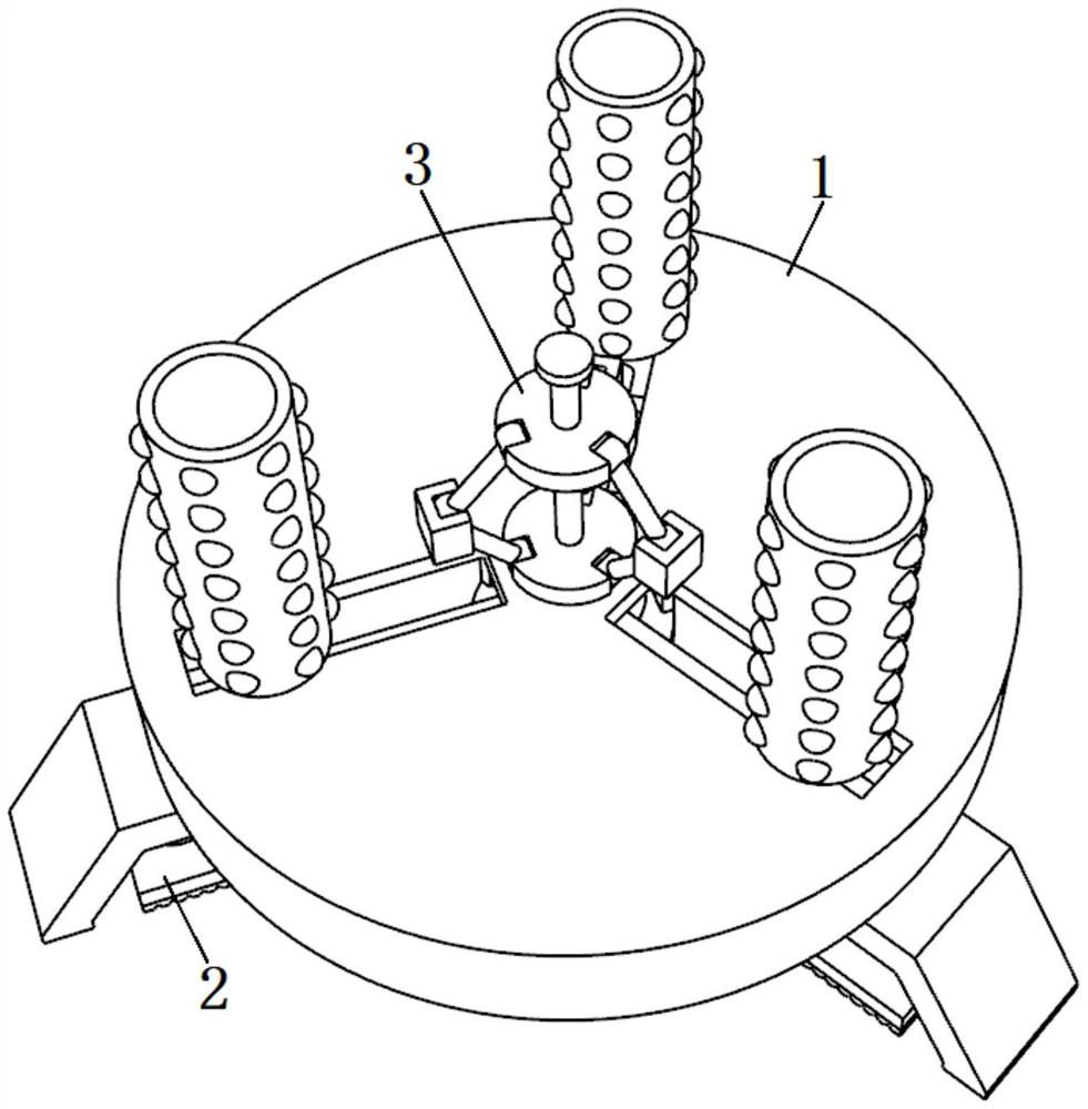
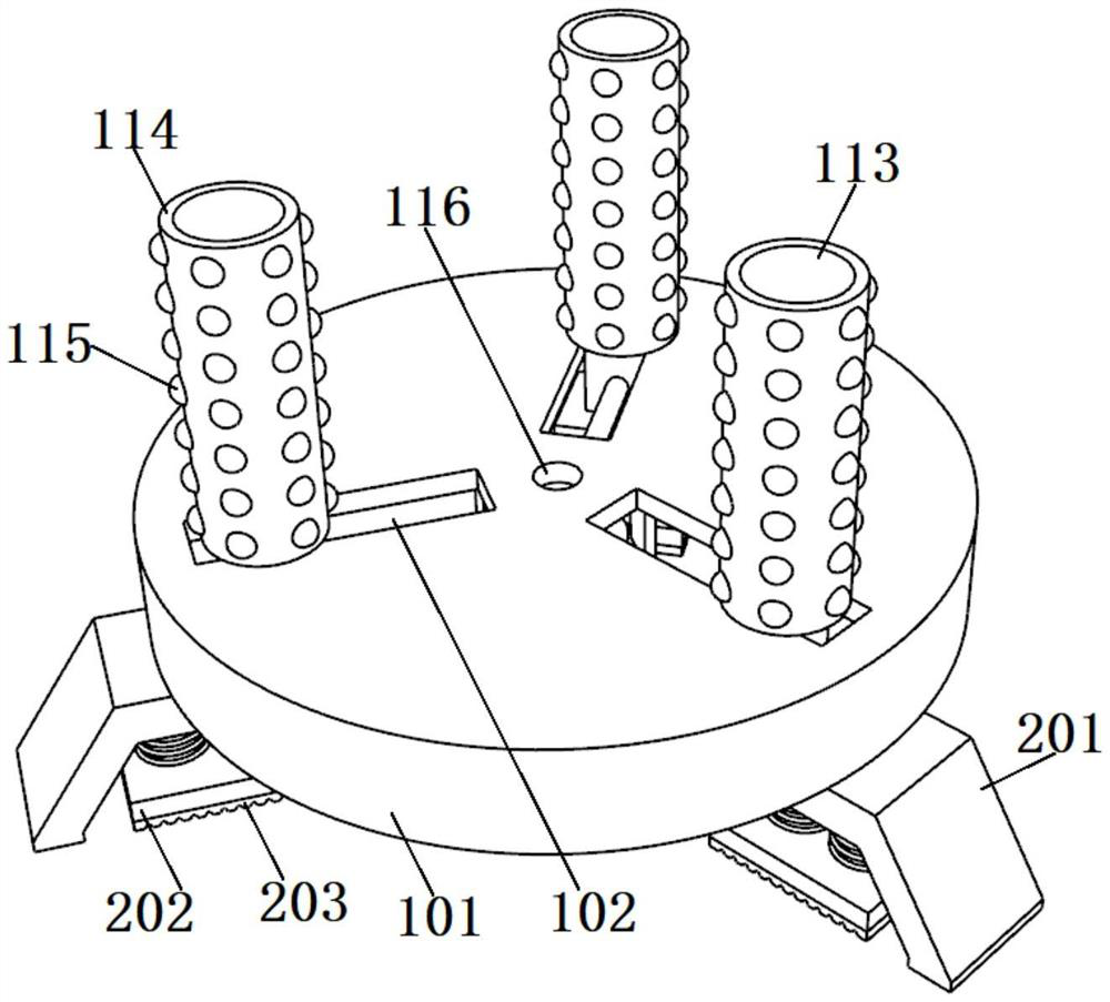
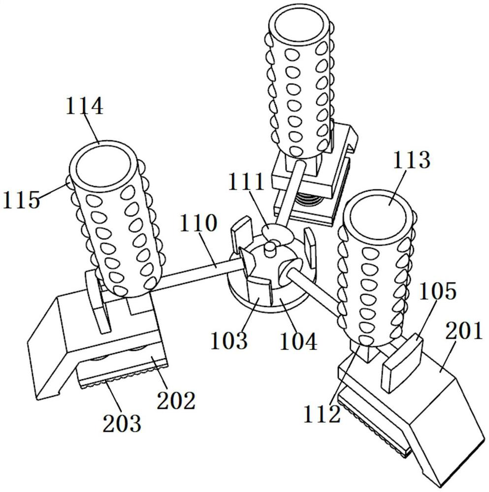
[0035] see Figure 1-8 , the present invention is a conventional column support and reinforcement device for building construction, comprising a clamping reinforcement mechanism 1, three support mechanisms 2 distributed in a circular array are fixed at the bottom of the clamping reinforcement mechanism 1, and the support mechanism 2 is used to clamp and reinforce Mechanism 1 lifts, so that the clamping reinforcement mechanism 1 is separated from the ground and...


PUM


Abstract

The invention discloses a conventional column body supporting and reinforcing device for building construction, and relates to the technical field of building equipment. The device comprises a clamping and reinforcing mechanism, wherein a plurality of supporting mechanisms distributed in a circular array mode are fixedly arranged at the bottom of the clamping and reinforcing mechanism, and a limiting mechanism is in threaded connection with the axis of the top of the clamping and reinforcing mechanism. According to the device, through utilizing a gear transmission mode, a first bevel gear in the device can synchronously drive a plurality of threaded screw rods to rotate, so that the threaded screw rods drive a plurality of round rollers to get close to one another by taking the first bevelgear as an axis in a screw rod transmission mode, and under the combined action of the plurality of round rollers, a column body placed on a supporting plate can be effectively clamped and fixed, sothat reinforcing and supporting operation of the column body for building construction is more trouble-saving and labor-saving, the fixing efficiency of the column body can be improved, and the safetyof the column body for building supporting in the using process can be effectively improved.

Description

technical field [0001] The invention belongs to the technical field of building equipment, and in particular relates to a conventional column support and reinforcement device for building construction. Background technique [0002] Construction refers to the assets made by man-made construction, which belongs to the category of fixed assets, including two categories: houses and structures. Housing refers to engineering buildings for people to live, work, study, produce, operate, entertain, store items and carry out other social activities. What is different from buildings are structures, which refer to engineering buildings other than houses, such as walls, roads, dams, wells, tunnels, water towers, bridges, and chimneys. [0003] Building construction refers to the production activities in the implementation stage of engineering construction. It is the construction process of various buildings. It can also be said to be the process of turning various lines on the design dr...

Claims


Application Information

Patent Timeline
Patent Type & Authority Applications(China)
IPC IPC(8): E04G21/24E04G21/32E04G25/02
CPCE04G21/24E04G21/32E04G25/02E04G2025/003E04G2025/006
Inventor 胡凡
Owner 徐小兵
Learn More