
Insulating ladder clamping device

A technology for clamping devices and insulating ladders, which is applied in the direction of measuring devices, measuring device shells, instruments, etc., can solve the problems of affecting the safety of workers, the instability of insulating ladder tests, and the inability to fix insulators, etc., to ensure safety, simple structure, The effect of easy operation

Active Publication Date: 2018-06-08
WUHU HONGKUN AUTO PARTS
View PDF10 Cites 0 Cited by
  • Summary
  • Abstract
  • Description
  • Claims
  • Application Information

AI Technical Summary

Problems solved by technology

[0003] The purpose of the present invention is to solve the shortcomings in the prior art, such as: the current domestic insulation ladder withstand voltage test device cannot effectively fix the insulator during the test, resulting in instability during the test of the insulation ladder, prone to accidents, affecting Worker safety while proposing an insulating ladder holding device

Method used


Image

  • Insulating ladder clamping device
  • Insulating ladder clamping device
  • Insulating ladder clamping device

Examples


Embodiment 1

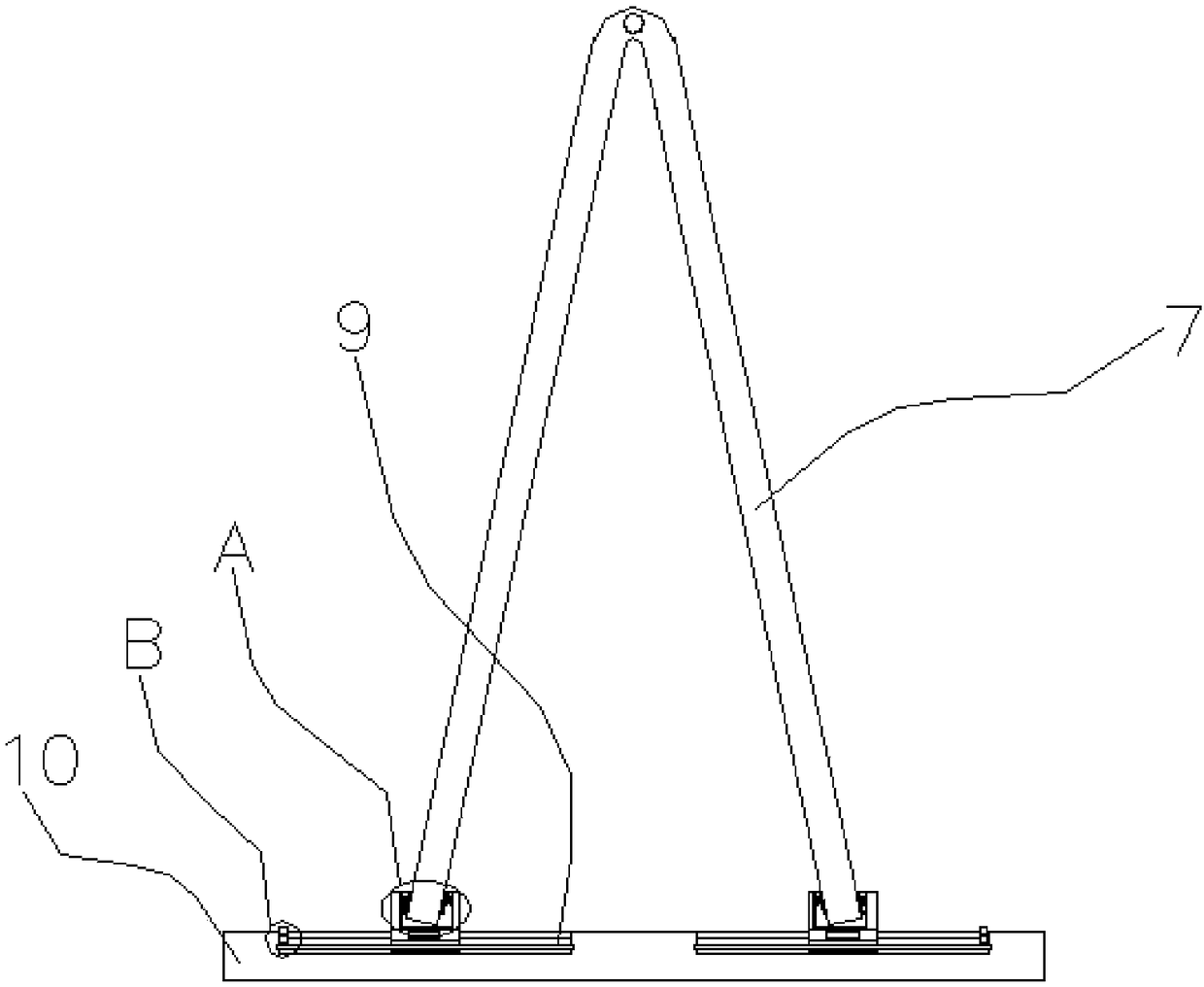
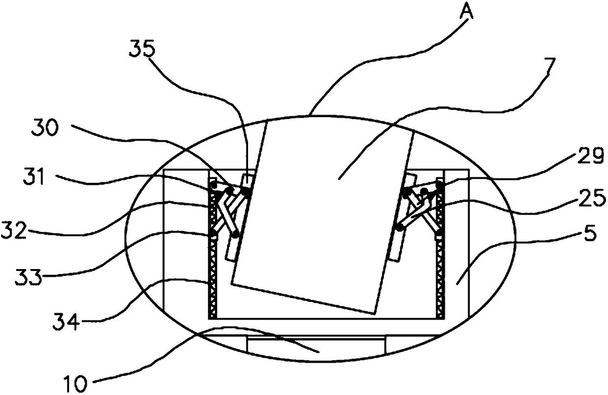
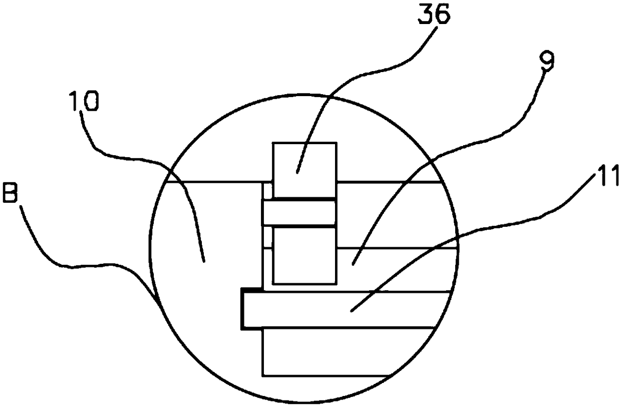
[0022] Embodiment 1: refer to Figure 1-3 , an insulation ladder clamping device, comprising a first placement plate 10, an insulation ladder 7 is arranged on the first placement plate 10, and the two ends of the insulation ladder 7 are respectively clamped on the first placement plate 10, and the first placement plate 10 The first chute 9 is provided on the top, and the first chute 9 is connected with the first threaded rod 11 in rotation. The first threaded rod 11 is provided with a plurality of fixing devices. The fixing device includes a card body 5, and one end of the card body 5 is threaded. Socketed on the first threaded rod 11, the inner wall of the first chute 9 is rotatably connected with an adjustment gear 36, the adjustment gear 36 is arranged on the first threaded rod 11, and there is a thread between the first threaded rod 11 and the adjustment gear 36 Connection, the user can drive the first threaded rod 11 to rotate by rotating the adjustment gear 36, thereby r...

Embodiment 2

[0023] Embodiment 2: refer to Figure 2-8, the present invention is applied to a kind of insulating ladder withstand voltage test device, comprising a guide rail 20, the bottom of the guide rail 20 is provided with a base 21, the guide rail 20 is provided with a second chute 14, and the inner wall of the second chute 14 is rotatably connected with The second threaded rod 19, the second threaded rod 19 is provided with a second placing plate 15, the bottom of the second placing plate 15 is provided with a sliding device, the second placing plate 15 is slidably connected with the second threaded rod 19 by a sliding device, The second placement plate 15 is provided with a first placement plate 10, a lifting device is provided between the first placement plate 10 and the second placement plate 15, and a driving device is provided on the second placement plate 15, and the sliding device includes a pair of slide blocks 38, the slide block 38 is fixedly connected with the bottom of t...


PUM


Abstract

The invention discloses an insulating ladder clamping device comprising a first placing plate which is provided with an insulating ladder. The two ends of the insulating ladder are clamped on the first placing plate. First threaded rods are provided with multiple fixing devices. Each fixing device comprises a clamp body. The first placing plate is provided with first chutes. The first threaded rods are rotatably connected in the first chutes. One end of the clamp body sleeves the first threaded rod in a threaded way. The clamp body is internally provided with a fixing groove. The internal wallof the fixing groove is symmetrically provided with connecting devices. One end of the insulating ladder is inserted in the fixing groove. The insulating ladder clamping device is simple in structureand convenient to operate, and the insulating ladder can be effectively fixed and clamped by the fixing devices so that the test stability can be guaranteed, the safety of the work personnel can alsobe guaranteed and the accident can be avoided.

Description

technical field [0001] The invention relates to the technical field of withstand voltage test devices, in particular to an insulation ladder clamping device. Background technique [0002] The insulation ladder is a safe climbing tool for the power system. It is mainly used for the inspection, maintenance and new construction of the power line to prevent and protect the personal safety of the staff and avoid the risk of electric shock. DL560-95 Electric Industry Safety Work Regulations stipulates that an electrical test should be carried out every 12 months for insulated hard ladders. The high-voltage test device cannot effectively fix the insulator during the test, resulting in instability during the test of the insulation ladder, prone to accidents, and affecting the safety of the staff. Contents of the invention [0003] The purpose of the present invention is to solve the shortcomings in the prior art, such as: the current domestic insulation ladder withstand voltage t...

Claims


Application Information

Patent Timeline
Patent Type & Authority Applications(China)
IPC IPC(8): G01R1/04G01R31/12
CPCG01R1/0425G01R31/12
Inventor 黄浩
Owner WUHU HONGKUN AUTO PARTS
Learn More