Vibration prevention and reduction structure

A technology of mounting seat and connecting rod, applied in the direction of low internal friction spring, etc., can solve the problems of vibration absorption, vibration generation, equipment damage, etc., to ensure the effect of shock absorption

Inactive Publication Date: 2021-02-26
ZHENGZHOU RAILWAY VOCATIONAL & TECH COLLEGE
View PDF0 Cites 1 Cited by
  • Summary
  • Abstract
  • Description
  • Claims
  • Application Information

AI Technical Summary

Problems solved by technology

[0002] Vibration will be generated during the operation of the equipment. Working in a vibrating environment will not only generate a lot of noise, but also cause damage to the equipment and affect the practical life of the equipment. Therefore, it is necessary to set up a shock-absorbing mechanism
[0003] However, the existing shock absorbing mechanism usually can only achieve one-way shock absorption, and when the equipment is subjected to multi-directional vibration, it cannot absorb the vibration well, which in turn affects the service life of the equipment. Therefore, a shock absorber is now provided structure to solve the technical problem

Method used


Image

  • Vibration prevention and reduction structure
  • Vibration prevention and reduction structure
  • Vibration prevention and reduction structure

Examples


Embodiment 1

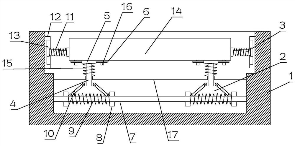
[0022] see Figure 1~3 , in Embodiment 1 of the present invention, it is a structural diagram of a shock-proof and shock-absorbing structure provided by the embodiment of the present invention, including: a base 1 and a mounting seat 14, the mounting seat 14 is arranged in the inner groove of the base 1, and the Mounting seat 14 is used for installing equipment;

[0023] Both sides of the bottom of the mounting seat 14 are respectively installed on the bottom of the base 1 through the first shock absorbing assembly 2, and the two sides of the first shock absorbing assembly 2 are respectively connected to the inner side wall of the base 1 through the second shock absorbing assembly 3; One end of the second damping assembly 3 is fixedly installed on the mounting base 14, and the other end is slid up and down and arranged on the side wall of the base 1;

[0024] The first damping assembly 2 includes a connecting rod 4, the upper end of the connecting rod 4 is fixedly installed w...

Embodiment 2

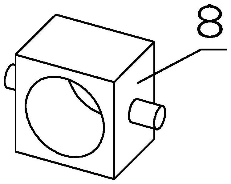
[0027] see Figure 1~3 The main difference between this embodiment 2 and embodiment 1 is that the two sides of the lower end of the connecting rod 4 are respectively rotated and installed with connecting rods 10, and the ends of the connecting rods 10 on both sides away from the connecting rod 4 are respectively rotated and sleeved in two slip rings. 8, the two slip rings 8 are slidingly sleeved on the second slide bar 7, and the second slide bar 7 is fixedly installed inside the base 1, and the two slip rings 8 are elastically sleeved on the second slide bar 7 , and then when the connecting rod 4 is vibrated, the vibration is transmitted to the slip ring 8 for secondary absorption, thereby realizing two-stage shock absorption.

[0028] The two slip rings 8 at the bottom of the connecting rod 4 are connected by the first elastic member 9, and the first elastic member 9 is sleeved on the outside of the second slide bar 7, and then the two slip rings 8 are elastically mounted on...


PUM


Abstract

The invention is applicable to the technical field of vibration reduction, and provides a vibration prevention and reduction structure. The vibration prevention and reduction structure comprises a base and a mounting base, wherein the mounting base is arranged in a groove in the base; the two sides of the bottom of the mounting base are mounted at the bottom of the base through first vibration reduction assemblies respectively, and the two sides of each first vibration reduction assembly are connected with the inner side wall of the base through second vibration reduction assemblies respectively; one end of each second vibration reduction assembly is fixedly installed on the mounting base, and the other end of each second vibration reduction assembly is arranged on the side wall of the base in an up-down sliding mode; each first vibration reduction assembly comprises a connecting rod, an upper connecting base is fixedly installed at the upper end of each connecting rod, the upper connecting bases are arranged at the bottom of the mounting base in a left-right sliding mode, the connecting rods penetrate through a support rod fixedly installed on the base, and each connecting rod issleeved with a second elastic piece; the upper end and the lower end of each second elastic piece are fixedly installed on the corresponding upper connecting base and the support rod respectively; andthe lower ends of the connecting rods are arranged to be connected with a second sliding rod through vibration reduction connecting pieces.

Description

technical field [0001] The invention relates to the technical field of shock absorption, in particular to a shock-proof and shock-absorbing structure. Background technique [0002] Vibration will be generated during the operation of the equipment. Working in a vibrating environment will not only generate a lot of noise, but also cause damage to the equipment and affect the practical life of the equipment. Therefore, it is necessary to set up a shock-absorbing mechanism. [0003] However, the existing shock absorbing mechanism usually can only achieve one-way shock absorption, and when the equipment is subjected to multi-directional vibration, it cannot absorb the vibration well, which in turn affects the service life of the equipment. Therefore, a shock absorber is now provided structure to solve this technical problem. Contents of the invention [0004] The object of the present invention is to provide a shock-proof and shock-absorbing structure to solve the problems rai...

Claims


Application Information

Patent Timeline
Patent Type & Authority Applications(China)
IPC IPC(8): F16F3/04
CPCF16F3/04
Inventor 黄莉袁媛徐金帅谢小山
Owner ZHENGZHOU RAILWAY VOCATIONAL & TECH COLLEGE
Why Eureka
Try Eureka