Improved reaction rod with joint assembly

A reaction rod, an improved technology, applied to springs made of plastic materials, springs/shock absorbers, mechanical equipment, etc., can solve the problems of high production cost, complicated processing technology, detachment, etc., and achieve the goal of saving energy and resources Effect

Active Publication Date: 2011-12-07
QUANZHOU XINLONG AUTOMOBILE PARTS MFG CO LTD
View PDF6 Cites 1 Cited by
  • Summary
  • Abstract
  • Description
  • Claims
  • Application Information

AI Technical Summary

Problems solved by technology

[0004] 1. The shock-absorbing part (elastomer) of the joint assembly is made by adding chemical raw materials to the rubber and heating and vulcanizing. The vulcanized rubber is filled in the cavity between the support pin and the outer casing and bonded to form a relatively integrated body. Once the external force is too large during use, the rubber is easy to separate from the supporting pin or the outer casing, and eventually the supporting pin and the outer casing are separated, which brings great hidden dangers to the safety of the vehicle.
[0005] 2. The damping part (elastomer) of the joint assembly is formed by heating and vulcanizing natural rubber with toxic chemical raw materials. Not only the processing technology is complicated, but the production cost is high, and it causes waste of resources and energy, and also causes air pollution.
[0008] Although this invention patent overcomes the main problems of the above-mentioned original joint assembly in actual use, because the steel wire spring is used instead of rubber as the shock-absorbing material, the shock-absorbing force is small, and there is a disadvantage that the steel wire spring is easy to fatigue and fracture , resulting in a short service life; although in order to prevent the steel wire spring from falling off, the present invention welds a fixed baffle at both ends of the support pin during assembly, but the fixed baffle is only used to prevent the steel wire spring from falling off in the axial direction and has no position-limiting effect. There is no common damping device with other components, and the damping effect is still unsatisfactory

Method used


Image

  • Improved reaction rod with joint assembly
  • Improved reaction rod with joint assembly
  • Improved reaction rod with joint assembly

Examples


Embodiment 1

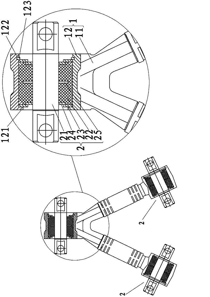
[0029] The improved reaction bar belt joint assembly of the present invention, the embodiment is as image 3 As shown, it includes a reaction rod 1 and a joint assembly 2 , the reaction rod 1 has a shaft 11 and a head 12 connected to the end of the shaft, and the joint assembly 2 is embedded and fixed in the head 12 .

[0030] In this embodiment, the reaction rod 1 adopts a V-shaped structure, and its shaft 11 is V-shaped with three ends, and the three ends are respectively connected with rod heads 12 .

[0031] One axial end of the rod head 12 has a rod head flange 121, and the other axial end of the rod head 12 is provided with a locking groove 122, and a clip spring 123 is embedded in the clip groove 122, through which the rod head flange 121 and the clip spring 123 will The joint assembly 2 is limited and fixed in the rod head 12 .

[0032] The joint assembly 2 includes a support pin 21 , an elastic body 22 , a rod head rigid limit baffle 23 , a support pin rigid limit ba...

Embodiment 2

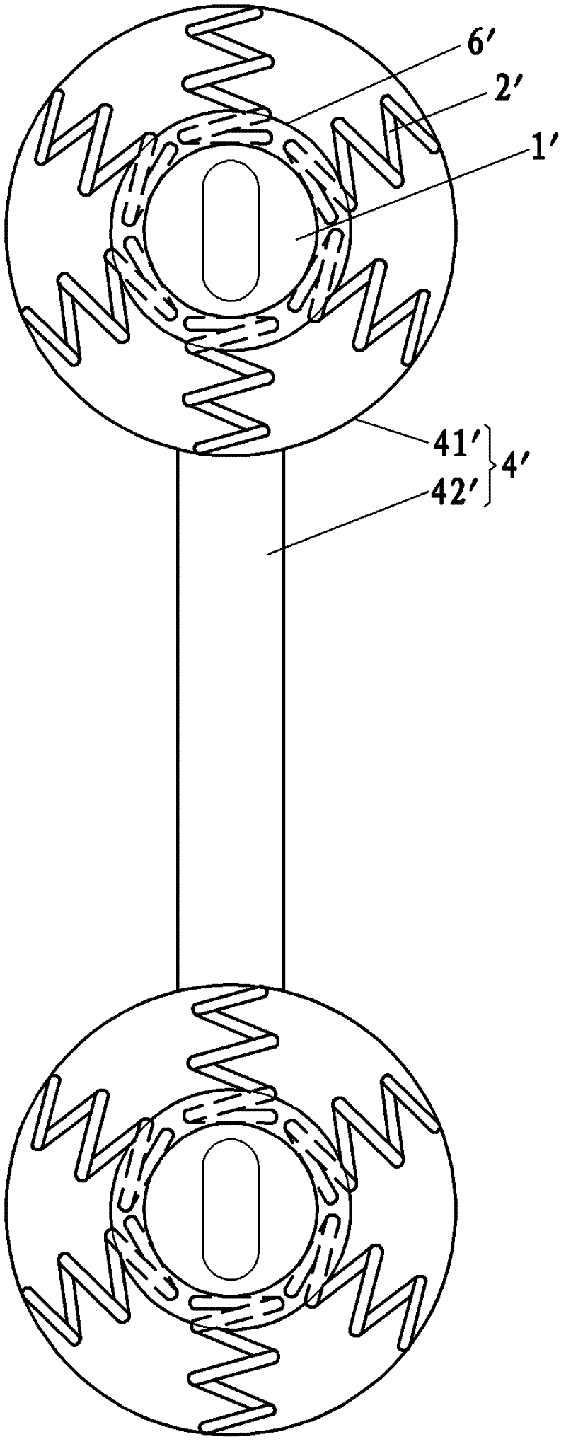
[0037] The improved reaction rod belt joint assembly of the present invention, the second embodiment is as Figure 4 As shown, the difference between it and the first embodiment is that the reaction rod 1 adopts an I-shaped structure, and its shaft 11 is I-shaped with two ends.

Embodiment 3

[0039] The improved reaction rod with joint assembly of the present invention, the third embodiment is as Figure 5 As shown, it includes a reaction rod 1 and a joint assembly 2 , the reaction rod 1 has a shaft 11 and a head 12 connected to the end of the shaft, and the joint assembly 2 is embedded and fixed in the head 12 .

[0040] In this embodiment, the reaction rod 1 adopts a V-shaped structure, and its shaft 11 is V-shaped with three ends, and the three ends are respectively connected with rod heads 12 .

[0041] One axial end of the rod head 12 has a rod head flange 121, and the other axial end of the rod head 12 is provided with a locking groove 122, and a clip spring 123 is embedded in the clip groove 122, through which the rod head flange 121 and the clip spring 123 will The joint assembly 2 is limited and fixed in the rod head 12 .

[0042] The joint assembly 2 includes a support pin 21 , an elastic body 22 , a rod head rigid limit baffle 23 , a support pin rigid l...


PUM


Abstract

The invention discloses an improved-type counteractive rod with a joint assembly. The rod comprises the counteractive rod and the joint assembly which is embedded in and fixed in a rod head of the end part of the counteractive rod; the joint assembly comprises a bearing pin, an elastic body, a rod head rigid limit baffle plate, a bearing pin rigid limit baffle plate and a rigid internal fixed baffle plate; the bearing pin, the rod head and the bearing pin rigid limit baffle plate form an annular containing chamber for filling the elastic body, and a radial limit clearance is respectively arranged between the rod head, the bearing pin rigid limit baffle plate and the inner side wall of the rod head or the bearing pin; the rigid internal fixed baffle plate is fixedly arranged on the bearingpin and is positioned in the containing chamber, and separates the containing chamber axially into two parts which are relatively independent, and a radial limit clearance is arranged between the outer diameter of the rigid internal fixed baffle plate and the inner side wall of the rod head. After adopting the technical scheme, the shock absorption effect of the improved-type counteractive rod with the joint assembly is optimal, the elastic body can be effectively prevented from cracking and dropping off due to excessive tension, the structure is very stable, and the service life is longer.

Description

technical field [0001] The invention relates to a reaction bar belt joint assembly in a chassis rear suspension balance device of a vehicle carrier. Background technique [0002] The traditional reaction rod with joint assembly, its basic structure is as follows figure 1 As shown, it includes a supporting pin 1', an elastic body 2', an outer casing 3', an operating rod 4' and a snap ring 5'. The action rod 4 ′ includes a rod head 41 ′ and a rod body 42 ′. A flange 411 ′ is provided at one axial end of the rod head 41 ′, and a locking groove 412 ′ is provided at the other axial end. Inject natural rubber and chemical raw materials between the outer casing 3' and the supporting pin 1', heat and vulcanize to form the elastic body 2', and the elastic body 2' is solidified between the outer casing 4' and the supporting pin 1', so that the elastic body 2 'The support pin 1' and the outer casing 3' are glued together to form a relatively integral body, and the expansion and contr...

Claims


Application Information

Patent Timeline
Patent Type & Authority Applications(China)
IPC IPC(8): F16F1/38F16F15/04
Inventor 陈清欣
Owner QUANZHOU XINLONG AUTOMOBILE PARTS MFG CO LTD
Why Eureka
Try Eureka