Eureka AIR delivers breakthrough ideas for toughest innovation challenges, trusted by R&D personnel around the world.

Remote monitoring automatic refueling device

A technology of automatic refueling and remote monitoring, applied in the directions of engine components, engine lubrication, and lubricating parts, etc., can solve the problems of oil residue clogging of the filter screen, affecting the refueling efficiency, etc., to prevent clogging and accelerate the falling speed.

Inactive Publication Date: 2021-02-26
ZHANGQIU FENGYUAN MACHINERY
View PDF2 Cites 0 Cited by
  • Summary
  • Abstract
  • Description
  • Claims
  • Application Information

AI Technical Summary

Problems solved by technology

[0005] The purpose of the present invention is to solve the problems in the prior art that the filter screen is easily blocked by oil residue after a long time of use. Once blocked, it will affect the fueling efficiency, and the device does not involve how to facilitate the cleaning of the filtered oil residue. Shortcomings, and a remote monitoring automatic refueling device proposed

Method used


Image

  • Remote monitoring automatic refueling device
  • Remote monitoring automatic refueling device
  • Remote monitoring automatic refueling device

Examples


Embodiment 1

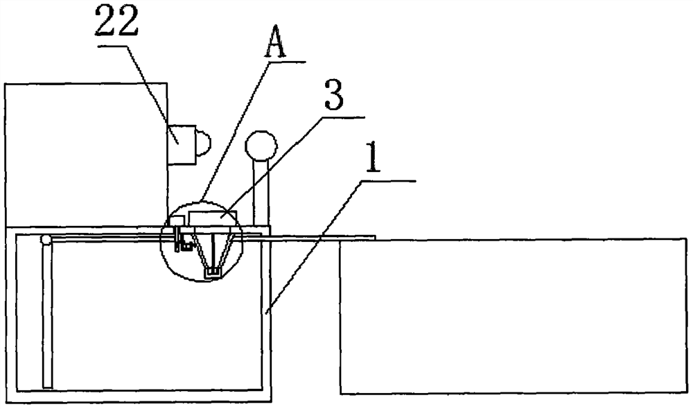
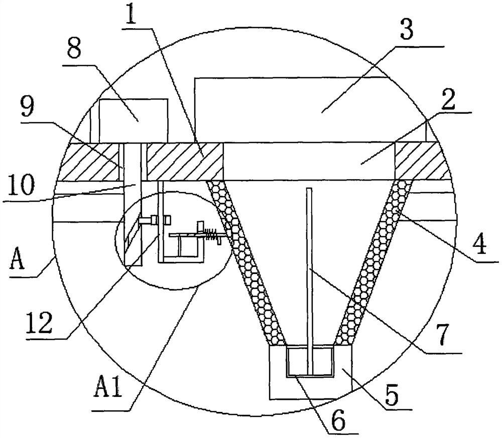
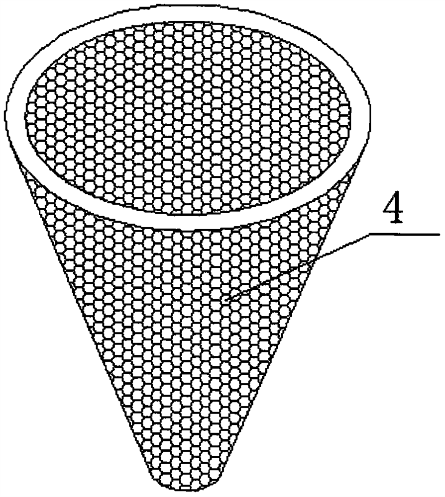
[0021]ReferenceFigure 1-4, A remote monitoring and automatic refueling device, including a fuel storage tank 1, a control box is arranged above the fuel storage tank 1, a fuel filler 2 is provided on the inner wall of the top side of the fuel storage tank 1, and a fuel tank cover 3 is provided above the fuel filler 2, a control box A camera 22 is fixedly installed on one side of the oil storage tank 1, a conical filter 4 is fixedly installed on the inner wall of the top side of the oil storage tank 1, the fuel filler 2 is located in the conical filter 4, and a fixed box is fixedly installed on the bottom side of the conical filter 4 5. A collection box 6 is placed in the fixed box 5. A pull rod 7 is fixedly installed on the inner wall of the bottom side of the collection box 6. The top end of the pull rod 7 extends into the cone-shaped filter screen 4, and the fuel tank cover 3 is opened to the fuel storage tank 1. Fill in the oil, the oil enters the conical filter 4 through the ref...

Embodiment 2

[0027]ReferenceFigure 1-4, A remote monitoring and automatic refueling device, including a fuel storage tank 1, a control box is arranged above the fuel storage tank 1, a fuel filler 2 is provided on the inner wall of the top side of the fuel storage tank 1, and a fuel tank cover 3 is provided above the fuel filler 2, a control box A camera 22 is fixedly installed on one side of the oil storage tank 1, a tapered filter 4 is fixedly installed on the inner wall of the top side of the oil storage tank 1, the fuel filler 2 is located in the tapered filter 4, and the bottom side of the tapered filter 4 is fixedly welded with a fixed box 5. A collection box 6 is placed in the fixed box 5. A pull rod 7 is fixedly welded on the bottom inner wall of the collection box 6. The top end of the pull rod 7 extends into the conical filter screen 4, and the fuel tank cover 3 is opened to the fuel storage tank 1. Fill in the oil, the oil enters the conical filter 4 through the refueling port 2, and i...


PUM


Abstract

The invention belongs to the field of machining, particularly relates to a remote monitoring automatic refueling device, and aims at solving the problems that after an existing device is used for a long time, a filter screen is prone to being blocked by oil residues, refueling efficiency is affected once the filter screen is blocked, and the device does not relate to how to conveniently clean thefiltered oil residues. The following scheme is proposed: the remote monitoring automatic refueling device comprises an oil storage tank; a control box is arranged above the oil storage tank; an oil filling port is arranged on the inner wall of the top side of the oil storage tank; an oil tank cover is arranged above the oil filling port; a camera is fixedly installed on one side of the control box; a conical filter screen is fixedly installed on the inner wall of the top side of the oil storage tank, and the oil filling port is located in the conical filter screen; and a fixed tank is fixedlyinstalled at the bottom side of the conical filter screen. According to the remote monitoring automatic refueling device provided by the invention, due to the fact that an impact rod is arranged, theimpact rod impacts the filter screen, the filter screen can be prevented from being blocked, the filter screen can be kept in an optimal filtering state, and the falling speed of the oil residues canbe increased.

Description

Technical field[0001]The invention relates to the technical field of mechanical processing, in particular to a remote monitoring automatic refueling device.Background technique[0002]For a long time, weaving machinery tends to run continuously, so we need to maintain these equipment from time to time and add lubricating oil to ensure its normal operation. Under the control of the high-precision electronic system, adjust the equipment according to actual needs. Various output oil states can be used to cooperate with production, which can effectively improve industrial production efficiency.[0003]The publication number CN206759628U discloses a patent for a remote monitoring device. Its structure includes a shell, a chip, an antenna pole, a fixed seat, a side panel, a microphone, a universal rotating chassis, a groove, and a scanning head. The chip is installed inside the shell and the antenna The rod is installed at the rear of the surface of the fixed seat, and the device can be used ...

Claims


Application Information

Patent Timeline
IPC IPC(8): F16N29/00F16N39/06F16N33/00
CPCF16N29/00F16N33/00F16N39/06
Inventor 景奉国潘荣常马永民
Owner ZHANGQIU FENGYUAN MACHINERY
Why Eureka
Eureka Blog
Learn More