Glasses leg

A technology for temples and temples, applied in the field of glasses, can solve the problems of easy falling off of glasses, easy wearing, and pain in the bridge of the nose, etc., and achieves the effects of novel structure, improved comfort, and avoidance of falling off.

Pending Publication Date: 2021-02-26
张文革
View PDF0 Cites 0 Cited by
  • Summary
  • Abstract
  • Description
  • Claims
  • Application Information

AI Technical Summary

Problems solved by technology

[0004] The existing glasses rely on the nose pads to support the frame, and use the temple hooks to hang on the ears to prevent the glasses from falling off. The bridge of the nose is more painful after wearing this kind of glasses for a long time, and it is easy to loosen when worn. When the wearer jumps, etc. The glasses are easy to fall off during activities, which is very inconvenient

Method used


Image

  • Glasses leg
  • Glasses leg
  • Glasses leg

Examples


Embodiment 1

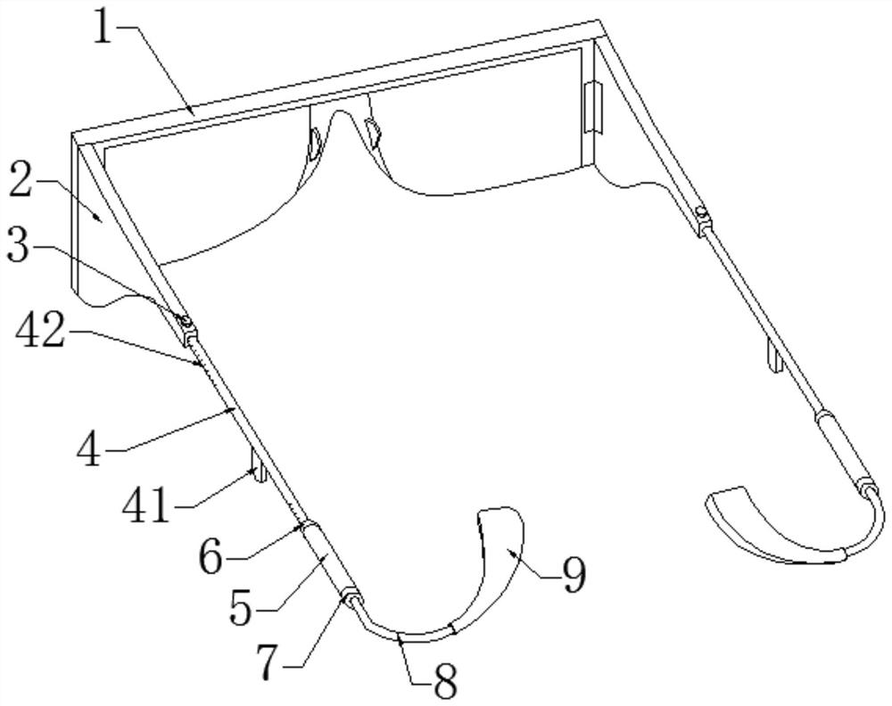
[0029] Such as figure 1 , Figure 4-Figure 6 As shown, a spectacle leg includes a spectacle frame arm 2 that can be hinged on both sides of the spectacle frame main body 1. The end of the spectacle frame arm 2 is inserted with a middle spectacle leg 4 and fixed by a thumb screw 3, which is threadedly mounted on the On the side wall of the end of the frame arm 2, the depth at which the middle mirror leg 4 is inserted into the frame arm 2 can be adjusted by turning the thumb screw 3, and then the length of the middle mirror leg 4 exposed to the frame arm 2 can be adjusted, and the middle lower end of the middle mirror leg 4 is integrally formed. The ear trip ear 41 is used to be stuck on the upper ear base of the ear, which is convenient for fixing the glasses. The other end of the middle mirror leg 4 is fixed with an extension sleeve 5 through a locking cap 6, and the end of the middle mirror leg 4 is inserted into the extension sleeve 5 , the length of the middle mirror leg 4...

Embodiment 2

[0033] Such as figure 2 As shown, the content of this embodiment is roughly the same as that of Embodiment 1, except that:

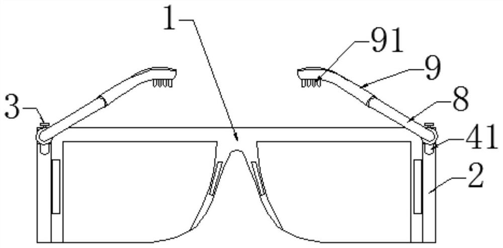
[0034] In this embodiment, the end of the anti-slip rubber sleeve 9 is an inclined flat structure, and the side of the anti-slip rubber sleeve 9 facing the scalp is provided with anti-slip combs 91, and the anti-slip combs 91 are inserted into the hair at the rear of the head to increase the tail mirror legs 8 fixed firmness.

Embodiment 3

[0036] Such as image 3 As shown, the content of this embodiment is roughly the same as that of Embodiment 1, except that:

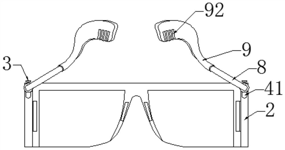
[0037] In this embodiment, the end of the anti-slip rubber sleeve 9 is a vertical flat structure, and the side of the anti-slip rubber sleeve 9 facing downward is formed with a comb groove 92. When wearing glasses, the tail mirror legs 8 move downward, and the rear sides of the head The hair can be stuck in the comb groove 92, improve the firmness that tail mirror leg 8 is fixed.


PUM


Abstract

The invention relates to the technical field of glasses, and particularly discloses glasses legs which comprise glasses frame arms capable of being hinged to the two sides of a glasses frame body, middle glasses legs are inserted into the ends of the glasses frame arms and fixed through hand screws, and ear stumbling lugs are integrally formed at the lower ends of the middles of the middle glasseslegs. A lengthening sleeve is fixed to the other end of the middle glasses leg through a locking cap, a tail glasses leg is fixed to the end of the lengthening sleeve through a fixing cap, and an anti-skid rubber sleeve is embedded into the end of the tail glasses leg. The invention have the beneficial effects that the structure is novel, the length of the glasses legs can be adjusted according to head shapes, and the glasses can be matched with different types of glasses frames; the glasses are fixed by the rear part of the head and the ears, so that the stress of the nose bridge is reduced,the pressure of the nose pad on the nose bridge is reduced or eliminated, and the wearing comfort of the glasses is improved; a user can adjust the length and the angle of the glasses legs accordingto the head shape of the user, the glasses are not prone to loosening when the user does activities such as jumping after wearing the glasses, falling off during strenuous exercise can be avoided, andthe use effect is good.

Description

technical field [0001] The invention relates to the technical field of glasses, in particular to a spectacle leg. Background technique [0002] Glasses are lens lenses embedded in the frame and worn in front of the eyes to improve vision, protect eyes or for decoration. Mirrors can correct a variety of vision problems, including nearsightedness, farsightedness, astigmatism, presbyopia or strabismus, amblyopia, etc. [0003] Glasses are composed of lenses and frames. Divided into myopia glasses, hyperopia glasses, reading glasses and astigmatism glasses, plain glasses, computer goggles, goggles, swimming goggles, night vision goggles, gaming goggles, gaming goggles, goggles, sunglasses, toy glasses, sunglasses 15 kinds. There are also special glasses for watching 3D stereoscopic images or virtual reality images. Other types of eyewear include goggles, sunglasses, swimming goggles, etc., which provide various protection for the eyes. [0004] The existing glasses rely on ...

Claims


Application Information

Patent Timeline
Patent Type & Authority Applications(China)
IPC IPC(8): G02C5/20G02C5/16G02C5/14
CPCG02C5/143G02C5/16G02C5/20
Inventor 张文革
Owner 张文革
Why Eureka
Try Eureka