Eureka AIR delivers breakthrough ideas for toughest innovation challenges, trusted by R&D personnel around the world.

Supporting assembly of automatic bagging machine

A technology for supporting components and bagging machines, which is applied in the direction of engine bases, supporting machines, mechanical equipment, etc., can solve problems such as collapse, hidden safety hazards, and damage to the inner wall of the joint, and achieve high firmness, simple structure, and protection of the inner wall. Effect

Inactive Publication Date: 2021-03-02
金恩斯智能装备(天津)有限公司
View PDF6 Cites 0 Cited by
  • Summary
  • Abstract
  • Description
  • Claims
  • Application Information

AI Technical Summary

Problems solved by technology

[0003] When the automatic bagging machine is working, it will generate a large downward force. At this time, a support component with good firmness is required. Since the vertical beam of the automatic bagging machine is made of high-quality aluminum profiles, and each profile The fast-insert fastening method is adopted at the joints. This kind of structural support component will damage the inner wall of the joint after multiple consecutive downward force impacts.
It is easy to cause a "crash" situation, and there are potential safety hazards

Method used


Image

  • Supporting assembly of automatic bagging machine
  • Supporting assembly of automatic bagging machine

Examples


Embodiment Construction

[0014] In order to make the technical means, creative features, goals and effects achieved by the present invention easy to understand, the present invention will be further described below in conjunction with specific illustrations.

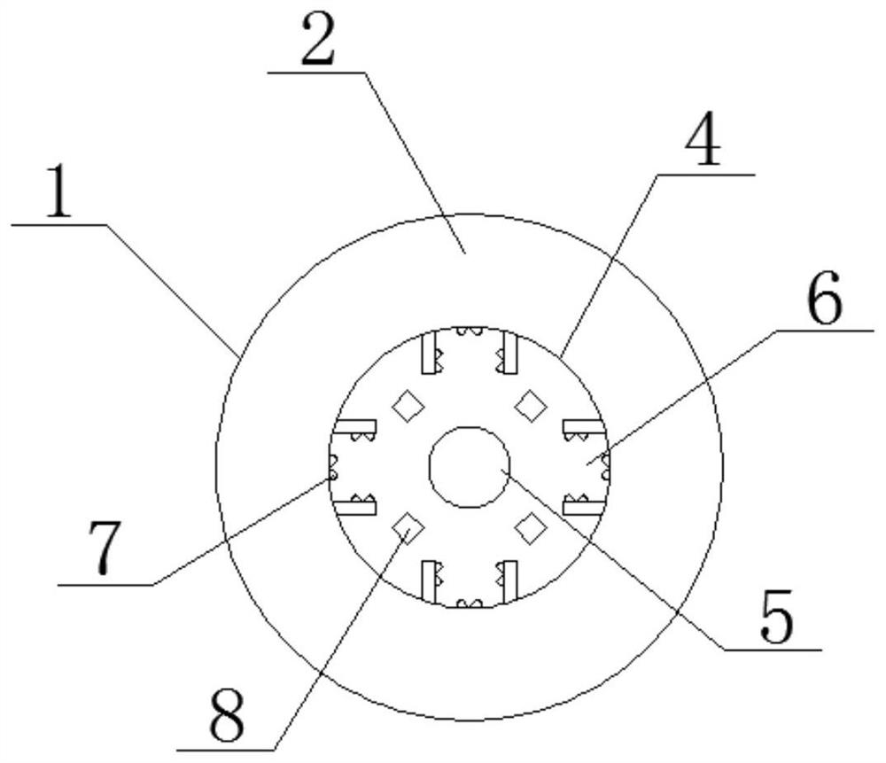
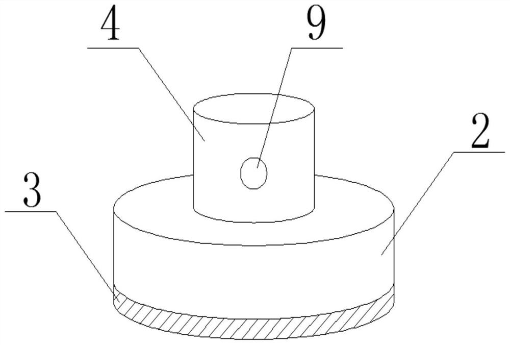
[0015] see figure 1 and figure 2 , a support assembly for an automatic bagging machine, comprising an assembly main body 1, a support chassis 2, an anti-slip pad 3, a support groove 4, a pillar 5, a card hole 6, a bump 7 and a plug groove 8, the bottom of the assembly main body 1 For the support chassis 2, the bottom of the support chassis 2 is provided with the anti-skid pad 3, the support chassis 2 is provided with the support groove 4, and the inner center of the support groove 4 is provided with the The pillar 5, the clamping hole 5 is provided on the outside of the pillar 5, the protrusion 7 is provided on the inside of the clamping hole 5, and the plug groove 8 is provided between the clamping holes 5. The support slot 4 is located in t...


PUM


Abstract

The invention discloses a supporting assembly of an automatic bagging machine. The supporting assembly comprises an assembly main body, a supporting chassis, a non-slip mat, a supporting groove, a supporting column, clamping holes, convex points and plug grooves. The supporting chassis is arranged at the bottom of the assembly main body, the non-slip mat is arranged at the bottom of the supportingchassis, and the supporting groove is arranged above the supporting chassis. The supporting column is arranged in the center of the interior of the supporting groove, the clamping holes are formed inthe outer side of the supporting column, the convex points are arranged on the inner sides of the clamping holes, and the plug grooves are formed between the clamping holes. The supporting assembly is simple in structure, corresponding clamping grooves are formed in the inner side of the supporting groove according to the special structure of an aluminum profile, the firmness of the supporting structure is higher, and the inner wall of a connecting part is protected.

Description

technical field [0001] The invention relates to the field of automatic bagging machines, in particular to a support assembly of the automatic bagging machine. Background technique [0002] my country is a large agricultural country, and the supporting machinery and equipment for agricultural production are also constantly updated and improved, among which the culture material bagging machine plays a powerful role in promoting the development of production. The vertical stamping bagging machine is matched with the mixer, conveyor belt, and storage machine to realize the factory production of the bagging line, which not only improves the production efficiency, but also greatly reduces the labor intensity and improves the bagging quality. [0003] When the automatic bagging machine is working, it will generate a large downward force. At this time, a support component with good firmness is required. Since the vertical beam of the automatic bagging machine is made of high-quality...

Claims


Application Information

Patent Timeline
Patent Type & Authority Applications(China)
IPC IPC(8): F16M5/00
CPCF16M5/00
Inventor 梅俊祥
Owner 金恩斯智能装备(天津)有限公司
Why Eureka
Eureka Blog
Learn More