Micro-power energy taking device, system and method based on direct-current corona ion current

A technology of DC corona and energy harvesting devices, which is applied in the direction of DC network circuit devices, circuit devices, electrical components, etc., can solve the problems of inability to meet the self-supply requirements of sensors, lack of wireless sensor energy harvesting devices, and unstable energy supply, etc., to achieve The effect of small size, realizing utilization and reducing the influence of electromagnetic interference

Inactive Publication Date: 2021-03-02
NORTH CHINA ELECTRIC POWER UNIV (BAODING)
View PDF0 Cites 0 Cited by
  • Summary
  • Abstract
  • Description
  • Claims
  • Application Information

AI Technical Summary

Problems solved by technology

This type of method has become the most widely used passive energy supply technology due to its simple structure, high reliability, and ease of application. However, since the energy source is an alternating electric field and a magnetic field, it cannot meet the requirements of sensors in high-voltage DC applications. self-supply requirements
At the same tim

Method used


Image

  • Micro-power energy taking device, system and method based on direct-current corona ion current
  • Micro-power energy taking device, system and method based on direct-current corona ion current
  • Micro-power energy taking device, system and method based on direct-current corona ion current

Examples


Example Embodiment

[0042] Embodiment one:

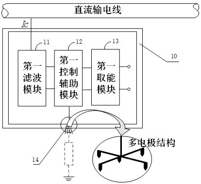
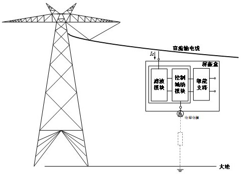
[0043] refer to figure 2 , the energy harvesting box is a unipolar energy harvesting box 1, and the connecting conductor is a metal conductor hook and a wire. The unipolar energy harvesting box 1 uses metal conductor hooks and other components to install on the DC transmission line for energy harvesting. The energy obtained can be Used by back-end sensing and data transmission devices.

[0044] For the first shielding box 10 in the unipolar energy harvesting box, it can be connected to the high potential device (DC transmission line) through the metal conductor hook, and connected to the energy harvesting device through the filter module through the metal wire. Specifically, the internal circuit functional unit of the unipolar energy harvesting box mainly includes a first filter module 11, a first control auxiliary module 12, and a first energy harvesting module 13, wherein the output branch of the first filter module 11 includes a low frequency comp...

Example Embodiment

[0053] Embodiment two:

[0054] refer to Figure 5 , the energy harvesting box is a bipolar energy harvesting cocoon 2, and the connecting conductor is an insulating fixing device, wherein the main part of the insulating fixing device is an insulating rope, which performs suspended energy harvesting by setting the energy harvesting cocoon in mid-air below the DC transmission line, The obtained energy can be used by the back-end sensing and data transmission devices. Since the corona itself is only related to the surrounding electric field (direction, magnitude), the bipolar energy harvesting cocoon provided by the embodiment of the present invention can reduce the direct connection with the main circuit circuit and improve the safety of the main power transmission equipment.

[0055] Compared with the unipolar energy harvesting box provided in the above embodiments, the bipolar energy harvesting cocoon is different in its internal circuit connection relationship. The interna...

Example Embodiment

[0065] Embodiment three:

[0066] Image 6 The micro-power energy harvesting method based on DC corona ion flow provided by the embodiment of the present invention.

[0067] refer to Image 6 , the micro-power energy harvesting method based on DC corona ion flow includes:

[0068] Step S101, using the connecting conductor to obtain the energy harvesting current of the direct current transmission line;

[0069] Step S102, filtering the current through the filter module to obtain branch component currents, wherein the branch component currents include low-frequency component currents and high-frequency component currents;

[0070] In step S103, a reference current and a low-power pulse signal are respectively formed according to the low-frequency component current and the high-frequency component current, and the auxiliary control module controls the corona electrode and the energy harvesting module to realize self-energy harvesting by the DC electric field by using the coron...


PUM


Abstract

The invention provides a micro-power energy taking device, system and method based on direct-current corona ion current, and the device comprises a connecting conductor connected with a high-potentialdevice, an energy taking box connected with the connecting conductor, and a corona electrode connected with the energy taking box, and the high-potential device is a direct-current transmission line.The energy taking box comprises a filtering module, a control auxiliary module and an energy taking module; the micro-power energy taking device is connected with a direct-current power transmissionline through the connecting conductor, takes energy through direct-current corona ion current released by the corona electrode, and utilizes the energy taking box to reduce electromagnetic interference generated by corona pulse so as to protect a sensing and data transmission device at the rear end. By utilizing the ion current generated by corona loss of the high-voltage direct-current power transmission line, the problem that a wireless sensor in a direct-current constant field is difficult to take energy is solved, and the device has the advantages of small size, flexibility in placement, stability in output and the like, and has a very strong application prospect.

Description

technical field [0001] The invention relates to the field of electrical engineering, in particular to a DC corona ion flow micropower energy harvesting device, system and method. Background technique [0002] As the power system gradually develops towards large capacity, high voltage and intelligence, safe and efficient operation is always the top priority. With the development of modern measurement, control and automation technology, sensor technology has received extensive attention and attention in the field of power systems. [0003] At present, traditional sensor devices are facing relatively large application limitations, and wireless sensors, as the most basic monitoring unit, have played an irreplaceable role in ensuring the safe and reliable operation of the power grid. With the rise of "digital new infrastructure", in order to improve maintenance-free Passive energy supply technology for sensors with the purpose of operating life has increasingly become a research...

Claims


Application Information

Patent Timeline
IPC IPC(8): H02J1/00H02J50/00H02J50/70
CPCH02J1/00H02J50/00H02J50/70
Inventor 石岩崔翔李学宝奇磊沈弘
Owner NORTH CHINA ELECTRIC POWER UNIV (BAODING)
Why Eureka
Try Eureka