Smooth blasting loading device
A technology of smooth blasting and charging, which is applied in blasting, mining equipment, earth-moving drilling, etc., can solve problems such as hidden dangers of insecurity, limited energy utilization rate of smooth blasting explosives, etc., and achieve the realization of utilization, blasting quality and economic benefits. Simultaneous improvement, simple and simple engineering design
- Summary
- Abstract
- Description
- Claims
- Application Information
AI Technical Summary
Problems solved by technology
Method used
Image
Examples
Embodiment 1
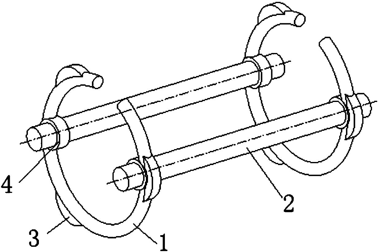
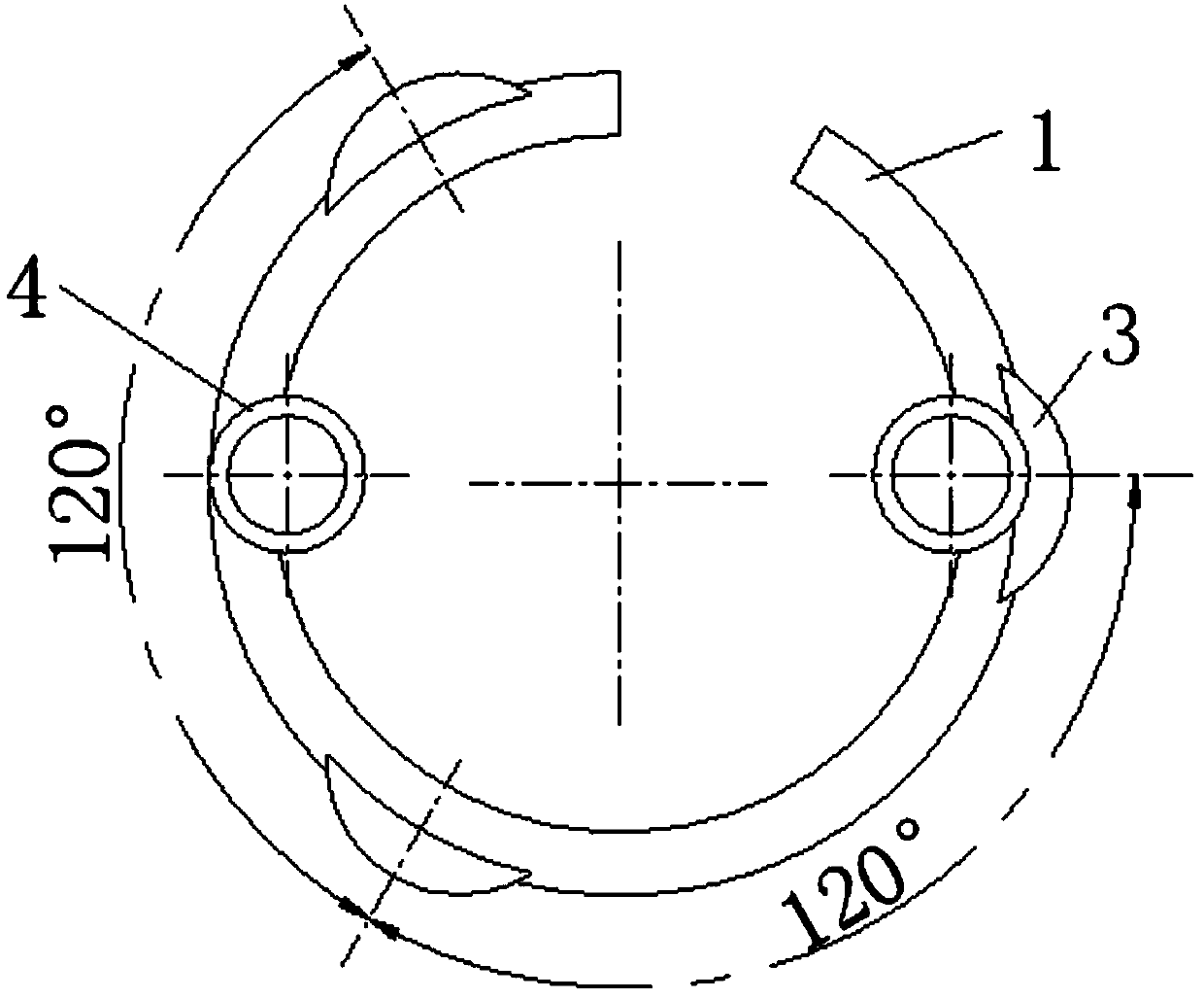
[0021] refer to Figure 1-2 , a smooth blasting charge device, which is coated on the smooth blasting explosive roll to ensure that the explosive roll is on the axis of the blast hole. The device includes two split rings 1 and two connecting rods 2. The outer rings Along the three convex points evenly distributed, the inner edge of the split ring 1 is symmetrically provided with fixing holes 4, and the two ends of each connecting rod 2 are respectively connected to the fixing holes 4 at the same position on the two split rings 1. A fixing hole 4 is located on the inner side of a protruding point 4, and two split rings 1 and two connecting rods 2 are manufactured and reassembled respectively.
[0022] The opening of the split ring 1 accounts for about 1 / 10 of the entire ring.
[0023] The outer edge of the split ring 1 has three raised bumps 3 uniformly distributed, and the extension of the bumps 3 is 2 mm.
[0024] The inner diameter of the fixing hole 4 is 2mm, the outer di...
Embodiment 2
[0028] refer to Figure 1-2 , a smooth blasting charge device, which is coated on the smooth blasting explosive roll to ensure that the explosive roll is on the axis of the blast hole. The device includes two split rings 1 and two connecting rods 2. The outer rings Along the three convex points evenly distributed, the inner edge of the split ring 1 is symmetrically provided with fixing holes 4, and the two ends of each connecting rod 2 are respectively connected to the fixing holes 4 at the same position on the two split rings 1. A fixing hole 4 is located on the inner side of a protruding point 4, and two split rings 1 and two connecting rods 2 are manufactured and reassembled respectively.
[0029] The opening of the split ring 1 accounts for about 1 / 6 of the entire ring.
[0030] The outer edge of the split ring 1 has three raised bumps 3 evenly distributed, and the extension of the bumps 3 is 6 mm.
[0031] The inner diameter of the fixing hole 4 is 6mm, the outer diamet...
Embodiment 3
[0035] refer to Figure 1-2 , a smooth blasting charge device, which is coated on the smooth blasting explosive roll to ensure that the explosive roll is on the axis of the blast hole. The device includes two split rings 1 and two connecting rods 2. The outer rings Along the three convex points evenly distributed, the inner edge of the split ring 1 is symmetrically provided with fixing holes 4, and the two ends of each connecting rod 2 are respectively connected to the fixing holes 4 at the same position on the two split rings 1. A fixing hole 4 is located inside a raised bump 4, and two split rings 1 and two connecting rods 2 are integrally cast.
[0036] The opening of the split ring 1 accounts for about 1 / 8 of the entire ring.
[0037] The outer edge of the split ring 1 has three raised bumps 3 evenly distributed, and the extension of the bumps 3 is 4mm.
[0038] The inner diameter of the fixing hole 4 is 4mm, the outer diameter of the connecting rod 2 matches the inner d...
PUM
| Property | Measurement | Unit |
|---|---|---|
| The inside diameter of | aaaaa | aaaaa |
Abstract
Description
Claims
Application Information
 - R&D
- Intellectual Property
- Life Sciences
- Materials
- Tech Scout
- Unparalleled Data Quality
- Higher Quality Content
- 60% Fewer Hallucinations
Browse by: Latest US Patents, China's latest patents, Technical Efficacy Thesaurus, Application Domain, Technology Topic, Popular Technical Reports.
© 2025 PatSnap. All rights reserved.Legal|Privacy policy|Modern Slavery Act Transparency Statement|Sitemap|About US| Contact US: help@patsnap.com


