Multi-band high-isolation coplanar antenna

A high-isolation, multi-band technology, applied in the microwave field, can solve the problems of unsatisfactory sub-band isolation index of ultra-wideband antenna, low isolation of multi-band co-array antenna, high design and processing costs, etc., to achieve simple and efficient engineering Effects of design, reliability and cost reduction, simple processing and installation

Active Publication Date: 2021-10-29
珠海中科慧智科技有限公司
View PDF9 Cites 2 Cited by
  • Summary
  • Abstract
  • Description
  • Claims
  • Application Information

AI Technical Summary

Problems solved by technology

[0010] The technical problem to be solved by the present invention is: how to solve the problem that the existing multi-band co-front antenna has low isolation, cannot work at the same time, and needs to add additional pre-selection filtering At the same time, it solves the problems that the isolation index cannot be satisfied and the radiation performance is reduced when designing the frequency band of the ultra-wideband antenna.

Method used


Image

  • Multi-band high-isolation coplanar antenna
  • Multi-band high-isolation coplanar antenna
  • Multi-band high-isolation coplanar antenna

Examples


Embodiment 1

[0026] This embodiment provides a technical solution: a multi-band high-isolation coplanar antenna, which uses a combination of three isolation methods such as spatial filtering, surface current blocking, and transmission filtering, and integrates antenna radiation performance and isolation indicators. design. The multi-band high-isolation coplanar antenna of the present invention includes low, medium, and high-band antennas and a common reflector, the low-frequency antenna includes a deformed cone antenna and a low-resistance filter structure, and the mid-frequency antenna includes a covered monopole An antenna and a high-resistance filter structure, the high-frequency antenna includes a variable cone antenna, a low-resistance filter structure, and a high-frequency isolation reflector.

[0027] The multi-band antennas, that is, low-, medium-, and high-frequency antennas are installed on the same reflector.

[0028] The low-frequency antenna adopts a deformed cone antenna and...

Embodiment 2

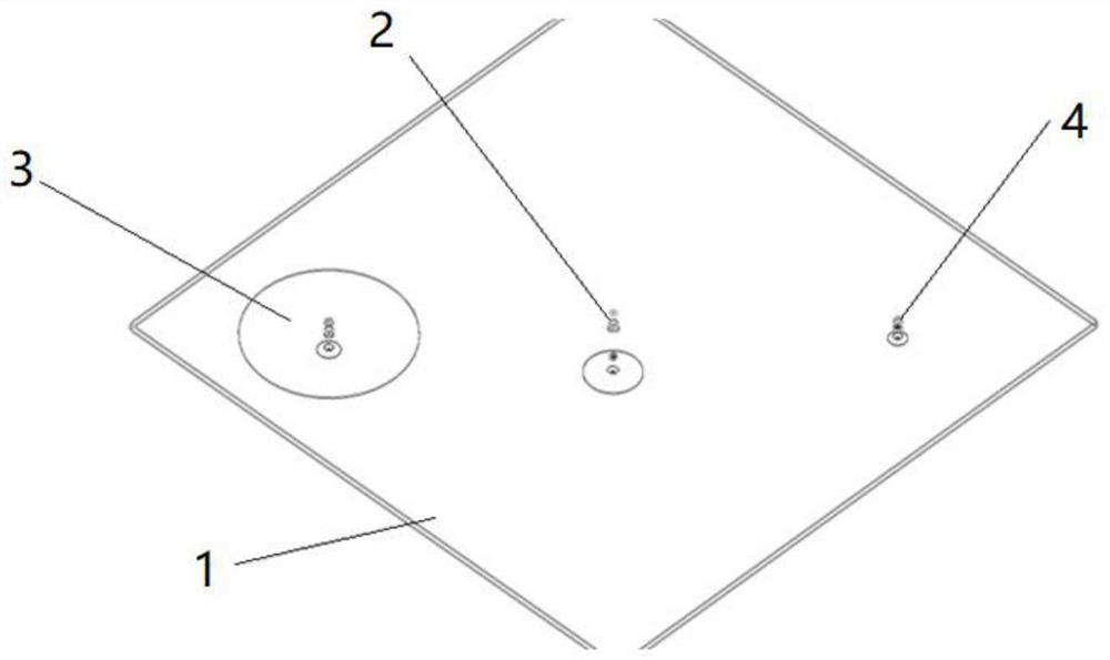
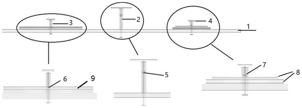
[0036] like figure 1 As shown, the multi-band high-isolation coplanar antenna of this embodiment consists of four parts, from bottom to top and from left to right, there are a common reflector 1, an intermediate frequency antenna 3, a low frequency antenna 2 and a high frequency antenna 4. like figure 2 As shown, the three-band antenna is set above the common reflector.

[0037] The low-frequency antenna 2, the intermediate-frequency antenna 3, and the high-frequency antenna 4 are spatially arranged in rows, the low-frequency antenna 3 is arranged in the middle of the shared reflector 1, and the intermediate-frequency antenna 3 and the high-frequency antenna 4 are arranged at both ends of the shared reflector 1.

[0038] The low-frequency antenna 2 is inside the feed structure and adopts an all-metal filter structure 5. The filter structure should not affect the impedance of the antenna itself when designing the filter structure. For the attenuation of high-frequency electro...


PUM


Abstract

The invention discloses a multi-band high-isolation coplanar antenna, and belongs to the technical field of microwaves. The multi-band high-isolation coplanar antenna comprises a low-band antenna, a middle-band antenna, a high-band antenna and a common reflecting plate, wherein the low-band antenna comprises a deformed frustum antenna and a low-resistance filtering structure, the middle-band antenna comprises a capped monopole antenna and a high-resistance filtering structure, the high-band antenna comprises a variable frustum antenna, a low-resistance filtering structure and a high-frequency isolation reflecting plate, and the common reflecting plate is a mounting plate of the low-band antenna, the middle-band antenna and the high-band antenna. According to the high-isolation coplanar antenna design method, the mode of combining three isolation modes of spatial filtering, surface current blocking and transmission filtering is adopted, the radiation performance of antennas of all bands is not affected while the isolation degree is improved, the machining is easy, the tolerance capacity is high, the machining cost of the whole system is reduced, and the multi-band high-isolation coplanar antenna is worthy of being used and popularized.

Description

technical field [0001] The invention relates to the field of microwave technology, in particular to a multi-band high-isolation coplanar antenna. [0002] The invention relates to a multi-band high-isolation coplanar antenna, in particular to a large-bandwidth, high-isolation coplanar antenna. [0003] The invention can be used for both transmitting and receiving signals. [0004] In military terms, it can be used as a broadband radar antenna. [0005] In terms of civil use, it can be used as a base station array antenna for multi-band communication. Background technique [0006] With the rapid development of electronic countermeasures and wireless communication technology, the demand for large bandwidth is becoming stronger and stronger. As the gateway of any wireless communication system, the performance of the antenna directly affects the communication quality of the system. When a single antenna cannot meet the broadband requirements, multi-band co-array antennas bec...

Claims


Application Information

Patent Timeline
Patent Type & Authority Applications(China)
IPC IPC(8): H01Q15/14H01Q1/52H01Q1/50
CPCH01Q15/14H01Q1/52H01Q1/50
Inventor 唐惠琼姜胜林
Owner 珠海中科慧智科技有限公司
Why Eureka
Try Eureka