
Antenna bending device

A bending device, antenna technology, used in metal processing, metal processing equipment, manufacturing tools, etc.

Pending Publication Date: 2021-03-09
KUNSHAN RUIXIANG XUNTONG COMM TECHCO
View PDF8 Cites 1 Cited by
  • Summary
  • Abstract
  • Description
  • Claims
  • Application Information

AI Technical Summary

Problems solved by technology

[0003] The object of the present invention is to provide an antenna bending device to at least solve the problem of how to improve the consistency of antenna bending

Method used


Image

  • Antenna bending device
  • Antenna bending device
  • Antenna bending device

Examples


Embodiment Construction

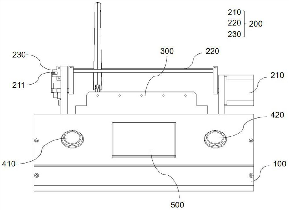
[0021] The antenna bending device proposed by the present invention will be further described in detail below with reference to the drawings and specific embodiments. It should be noted that all the drawings are in a very simplified form and use imprecise scales, and are only used to facilitate and clearly assist the purpose of illustrating the embodiments of the present invention. In addition, the structures shown in the drawings are often a part of the actual structures. In particular, each drawing needs to display different emphases, and sometimes uses different scales.

[0022] It should be noted that "first", "second", etc. in the specification, claims and description of the drawings of the present invention are used to distinguish similar objects in order to describe the embodiments of the present invention, and are not used to describe specific It is to be understood that the constructions so used are interchangeable under appropriate circumstances. Furthermore, the t...


PUM


Abstract

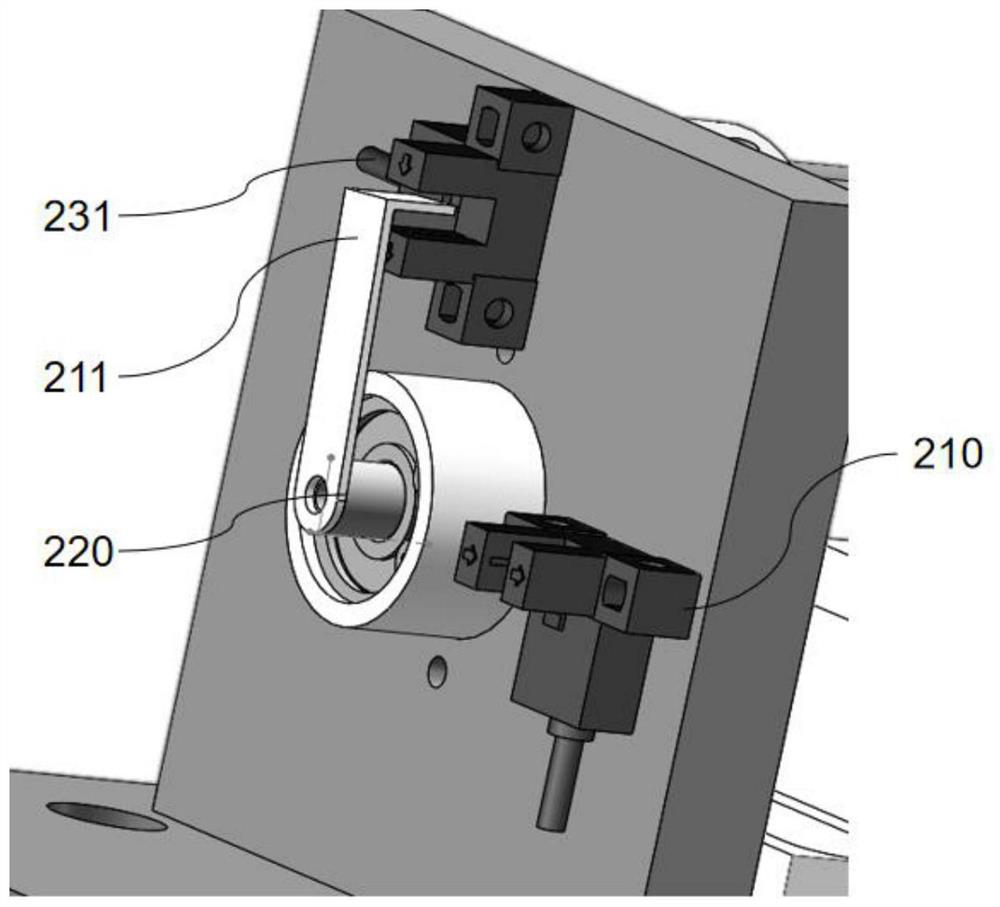
The invention provides an antenna bending device. The antenna bending device comprises a base, a bending unit, a fixed clamping unit and a control unit, wherein the bending unit and the fixed clampingunit are fixed on the base; the bending unit comprises a rotating motor, a bending shaft and a rotating limiter; the bending shaft is fixed on the rotating motor and is used for bending an antenna ata preset position under the driving of the rotating motor; the rotating limiter is used for limiting the rotating angle of the rotating motor; the fixed clamping unit is used for fixing the bottom ofthe antenna; and the control unit is used for controlling the bending unit and the fixed clamping unit to bend the antenna. When the antenna bending device is used, the antenna is fixed through the fixed clamping unit, the bending unit bends the antenna at a preset angle at a preset position, meanwhile, the control unit controls operation of the device, and due to the fact that the device automatically conducts bending operation, the manual operation is not needed, the manpower is saved, the consistency of antenna bending is good, and the problem of how to improve the consistency of antenna bending is solved.

Description

technical field [0001] The invention relates to the technical field of antenna manufacturing, in particular to an antenna bending device. Background technique [0002] Antenna bending, that is, bending processing of metal material tubes such as copper tubes used for wrapping in the antenna at a certain bending angle according to the usage. At present, the antenna bending process of antenna manufacturers mostly uses manual bending with the help of bending tooling. This method is not only greatly affected by labor, but also affected by the wear and tear of the tooling, which makes the antenna consistent after bending. poor. At the same time, in the case of batch operations, the existing method is manual counting, and the problems of missing counts and misremembering often occur. Contents of the invention [0003] The object of the present invention is to provide an antenna bending device to at least solve the problem of how to improve the consistency of antenna bending. ...

Claims


Application Information

Patent Timeline
Patent Type & Authority Applications(China)
IPC IPC(8): B21F1/00B21C51/00
CPCB21F1/00B21C51/00
Inventor 雍文生罗晓虎
Owner KUNSHAN RUIXIANG XUNTONG COMM TECHCO
Learn More