Stainless steel pipe clamping seat on cutting machine

A technology of stainless steel pipe and cutting machine, which is applied in the direction of pipe shearing device, shearing device, and accessory device of shearing machine, etc., which can solve the problems of long time consumption and achieve the effect of fast clamping

Inactive Publication Date: 2021-03-09
SHENZHEN SENSELEADER TECH DEV CO LTD
View PDF0 Cites 0 Cited by
  • Summary
  • Abstract
  • Description
  • Claims
  • Application Information

AI Technical Summary

Problems solved by technology

[0003] The sliding clamping seat drives the steel pipe feeding, and the steel pipe needs to be clamped on the sliding clamping seat. The clamping structure on the existing sliding clamping seat adopts two clamping blocks with V-shaped openings, and the clamping blocks are screwed with The lead screw, through the rotation of the lead screw, realizes the movement of the clamp block, and then realizes the clamping of the steel pipe, but when the clamping requires manual operation, the steel pipe needs to be centered during the clamping, and it takes a long time to replace the steel pipe; Design of sliding clamping seat for quick clamping

Method used


Image

  • Stainless steel pipe clamping seat on cutting machine
  • Stainless steel pipe clamping seat on cutting machine
  • Stainless steel pipe clamping seat on cutting machine

Examples


Embodiment Construction

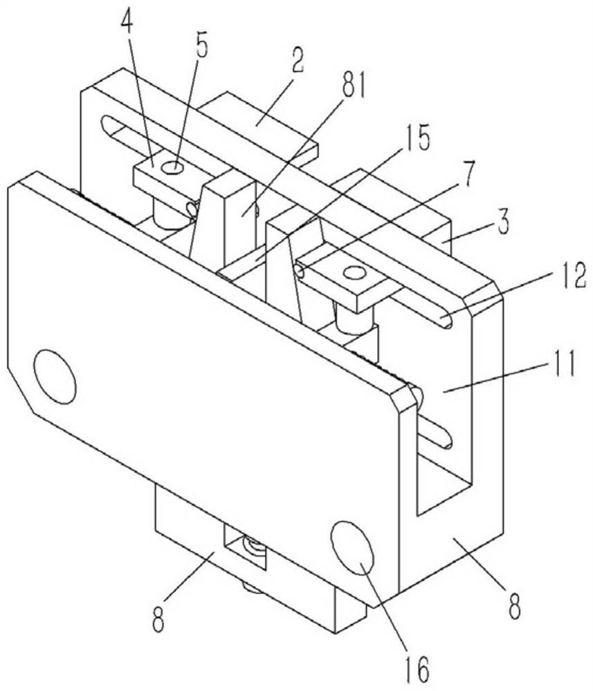
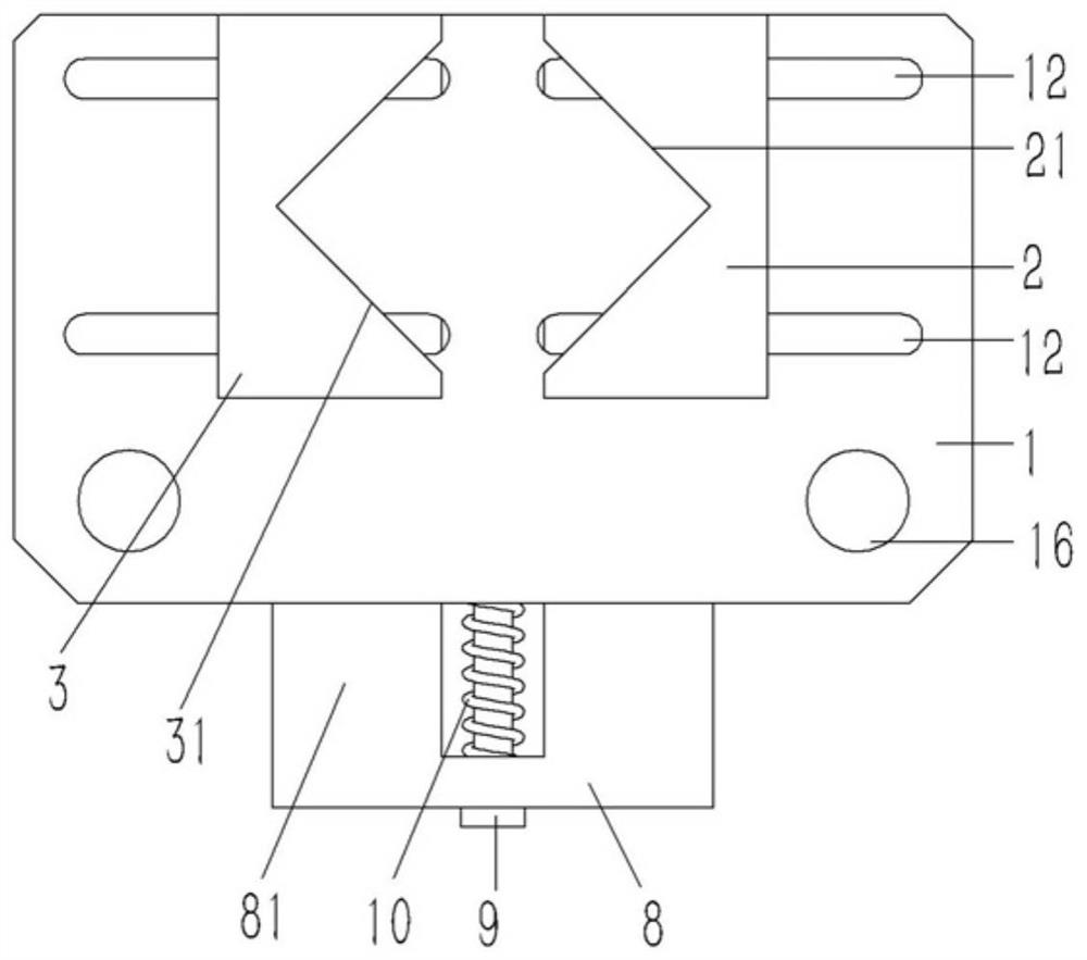
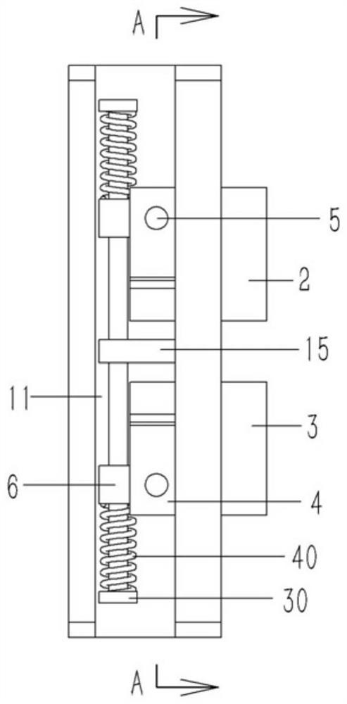
[0020] Example: see Figures 1 to 4 As shown, a stainless steel pipe clamp mounting seat on a cutting machine includes a rectangular base 1, the upper end surface of the base 1 is formed with a groove 11 that runs through the front and rear end surfaces of the base 1, and the right end surface of the base 1 Several longitudinal guide grooves 12 are formed and abut against the first clamping block 2 and the second clamping block 3, and the opposite end faces of the first clamping block 2 and the second clamping block 3 are respectively formed with V-shaped first clamping mouths 21 and the second jaw 31; the right end faces of the first clamping block 2 and the second clamping block 3 are fixedly connected with a number of guide blocks 4, and the guide blocks 4 pass through the guide groove 12 of the base 1 and are inserted and fixed with The vertical connecting shaft 5, the middle part of the connecting shaft 5 is sleeved and fixed with a tension block 6, and a T-shaped first g...


PUM


Abstract

The invention discloses a stainless steel pipe clamping seat on a cutting machine. The stainless steel pipe clamping seat comprises a rectangular base, a groove penetrating through the front end faceand the rear end face of the base is formed in the upper end face of the base, a plurality of longitudinal guide grooves are formed in the right end face of the base, a first clamping block and a second clamping block abut against the right end face of the base, and a first V-shaped clamping opening and a second V-shaped clamping opening are formed in the opposite end faces of the first clamping block and the second clamping block correspondingly; a plurality of guide blocks are fixedly connected to the right end faces of the first clamping block and the second clamping block correspondingly,the guide blocks penetrate through the guide grooves of the base to be fixedly connected with vertical connecting shafts in an inserted mode, tensioning blocks are fixed to the middles of the connecting shafts in an inserted and sleeved mode, T-shaped first guide rods are connected to the tensioning blocks in an inserted mode, the first guide rods penetrate through the tensioning blocks to be connected to a supporting plate in an inserted mode, and the supporting plate is formed on the inner side wall of the middle of the groove of the base; and first compressed springs are connected to the first guide rods in an inserted and sleeved mode, and the two ends of the first compressed springs abut against the heads of the first guide rods and the tensioning blocks correspondingly.

Description

technical field [0001] The invention relates to the technical field of stainless steel pipe cutting equipment, and more specifically relates to a stainless steel pipe clamp seat on a cutting machine. Background technique [0002] Stainless steel ferrule is a hollow long round steel material, which is widely used in industrial pipelines and mechanical structural components such as petroleum, chemical industry, medical treatment, food, light industry, mechanical instrumentation, etc. Among them, stainless steel anti-theft windows also need to use stainless steel pipe length. The standard stainless steel pipe length is about 6 meters. , using cutting equipment to cut, there is a cutting machine controlled by screw transmission, which uses the end of the steel pipe to be clamped and fixed by the sliding clamping seat screwed to the screw screw, and the sliding clamping seat moves to realize the conveying and feeding of the steel pipe. The transmission control of the through-hol...

Claims


Application Information

Patent Timeline
IPC IPC(8): B23D21/00B23D33/02
CPCB23D21/00B23D33/02
Inventor 倪志刚
Owner SHENZHEN SENSELEADER TECH DEV CO LTD
Why Eureka
Try Eureka