
Optical lens processing device using airbag clamping rotation to control polishing duration

A clamping technology for optical lenses and airbags, applied in grinding/polishing safety devices, grinding drive devices, manufacturing tools, etc., can solve the problems of low processing efficiency and achieve fast and efficient grinding, wear prevention, and fast clamping Effect

Inactive Publication Date: 2020-11-20
莫一全
View PDF11 Cites 1 Cited by
  • Summary
  • Abstract
  • Description
  • Claims
  • Application Information

AI Technical Summary

Problems solved by technology

[0005] Aiming at the deficiencies of the prior art, the present invention provides an optical lens processing device that utilizes the airbag to clamp and rotate to control the polishing time, which has the advantages of improving processing efficiency and ensuring processing quality, and solves the problem of low processing efficiency

Method used

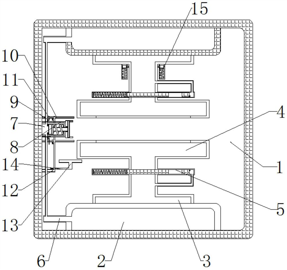

Image

  • Optical lens processing device using airbag clamping rotation to control polishing duration
  • Optical lens processing device using airbag clamping rotation to control polishing duration
  • Optical lens processing device using airbag clamping rotation to control polishing duration

Examples


Embodiment Construction

[0024] The following will clearly and completely describe the technical solutions in the embodiments of the present invention with reference to the accompanying drawings in the embodiments of the present invention. Obviously, the described embodiments are only some, not all, embodiments of the present invention. Based on the embodiments of the present invention, all other embodiments obtained by persons of ordinary skill in the art without making creative efforts belong to the protection scope of the present invention.

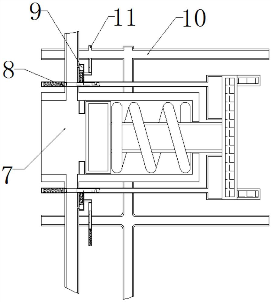
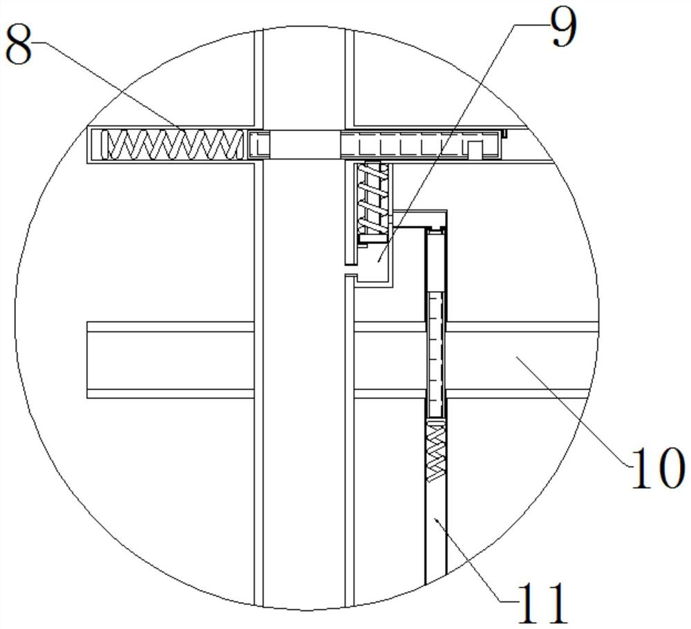
[0025] see Figure 1-4 , an optical lens processing device that uses airbag clamping and rotation to control the length of polishing, including a processing machine 1, a support base 2 is movably connected to the bottom of the processing machine 1, a rotating base 3 is movably connected to the top of the supporting base 2, and the rotating base 3 A clamping tube is movably connected with the clamping plate 4, and the upper part of the clamping plate 4 adopts a...


PUM


Abstract

The invention relates to the technical field of optical lens processing, and discloses an optical lens processing device using airbag clamping rotation to control polishing duration. The optical lensprocessing device comprises a processing machine; the bottom of the inside of the processing machine is movably connected with a support base; a rotating base is movably connected above the support base; a clamping plate is movably connected above the rotating base; a clamping track is movably connected below the clamping plate; the left side of the support base is movably connected with an air inlet pipe; and the left side of the interior of the processing machine is movably connected with a polishing track. According to the optical lens processing device using the airbag clamping rotation tocontrol the polishing duration provided by the invention, a movable pipe is used to further increase the air pressure inside the polishing track, a polishing slider is pushed to move to the right side to compress a polishing spring, so that a polishing plate is in contact with the edge position of an optical lens, the optical lens is polished, and during polishing, due to the polishing between the polishing plate and the optical lens, the effect of fast and efficient polishing is achieved, and the polishing duration is controlled by using the polishing temperature.

Description

technical field [0001] The present invention relates to the technical field of optical lens processing, and specifically relates to an optical lens processing device that utilizes an air bag to clamp and rotate to control the polishing time. Background technique [0002] Lenses refer to transparent materials with one or more curved surfaces made of optical materials such as glass or resin. There are many types of lenses, which can be divided into glass lenses, resin lenses, and PC lenses according to different types. [0003] In the process of lens processing, it generally needs to be cut and polished. After the cutting is completed, the edge needs to be polished in time. However, when grinding, the time control needs to be quite accurate. Too long grinding time will cause excessive wear of the lens. If the time is short, it cannot be polished completely. In view of the above problems, we propose an optical lens processing device that uses the airbag to clamp and rotate to c...

Claims


Application Information

Patent Timeline
IPC IPC(8): B24B13/00B24B41/06B24B47/22B24B55/03B24B55/06
CPCB24B13/00B24B41/06B24B47/22B24B55/03B24B55/06
Inventor 莫一全
Owner 莫一全
Learn More