Tool box special for vehicle ramp maintenance
A special tool and ramp technology, which is applied in the field of special toolboxes for vehicle ramp maintenance, can solve troubles and other problems, and achieve the effect of reducing friction
- Summary
- Abstract
- Description
- Claims
- Application Information
AI Technical Summary
Problems solved by technology
Method used
Image
Examples
Embodiment 1
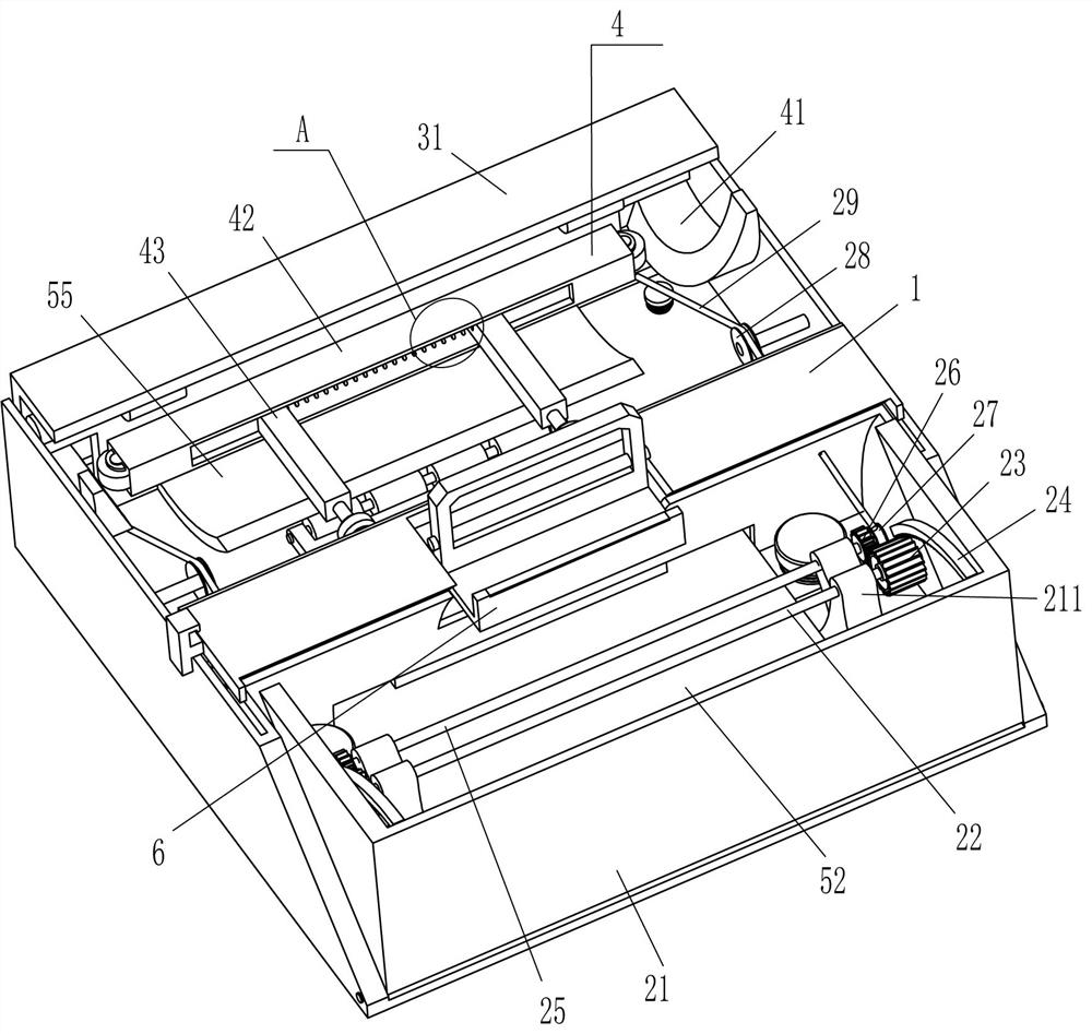
[0026] A special toolbox for vehicle ramp maintenance, such as Figure 1-Figure 4 As shown, it includes a frame body 1, a driving mechanism 2 and a placement mechanism 3. The right part of the frame body 1 is provided with a driving mechanism 2, and the left part of the frame body 1 is provided with a placement mechanism 3. The placement mechanism 3 is fixedly connected with the driving mechanism 2.
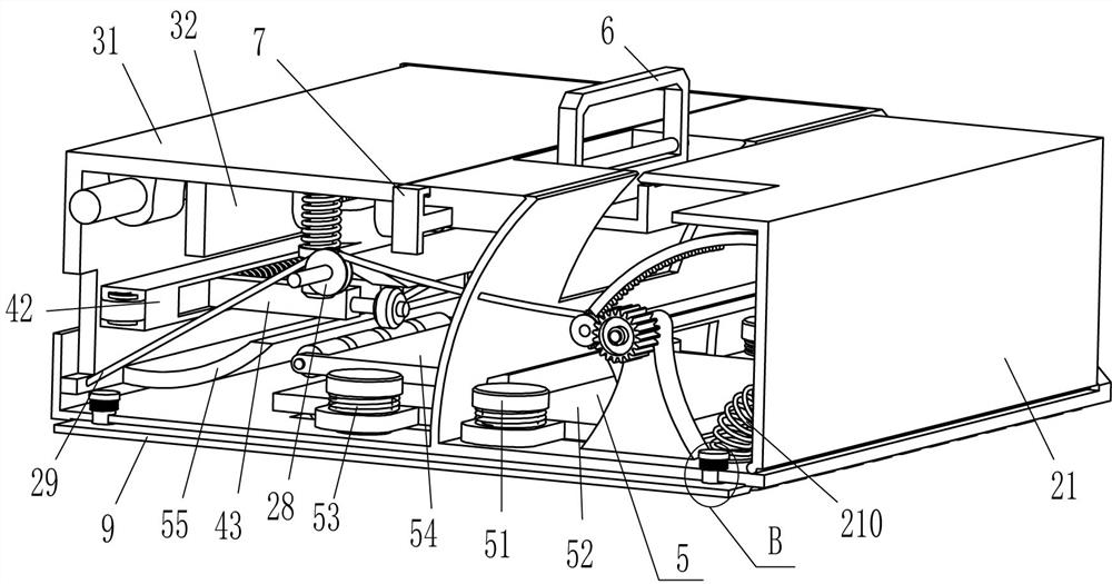
[0027] The driving mechanism 2 includes a swing frame 21, a first rotating shaft 22, a large gear 23, an arc rack 24, a second rotating shaft 25, a pinion 26, a winding wheel 27, a guide wheel 28, a backguy 29, a first spring 210 and Support seat 211, swinging frame 21 is rotatably connected between the lower side of the front and rear sides of the frame body 1, the swing frame 21 cooperates with the frame body 1, and the front and rear sides of the swing frame 21 are fixedly connected with arc-shaped racks 24. Both the front and rear parts on the right side of the inner bottom o...
Embodiment 2
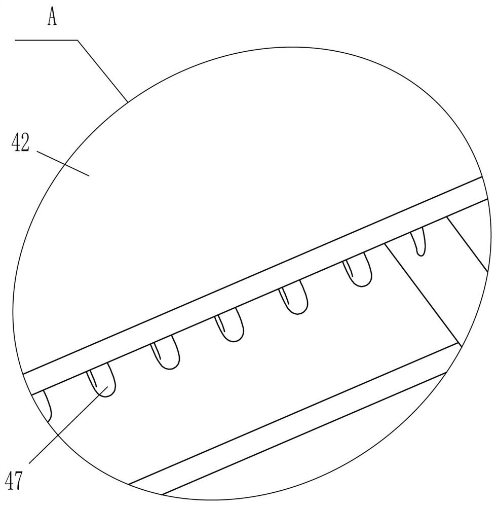
[0033] On the basis of Example 1, such as Figure 2-Figure 5 Shown, also include hold-down mechanism 4, hold-down mechanism 4 includes arc-shaped block 41, movable tube 42, L-shaped bar 43, vertical bar 44, trapezoidal block 45, second spring 46 and the 3rd spring 47, L Vertical rods 44 are fixedly connected to the front and rear symmetrically on the right side of the inner top of the template 31. A trapezoidal block 45 is slidingly provided between the vertical rods 44 on the front and rear sides. There is a second spring 46, and the second spring 46 is set on the vertical bar 44. A movable tube 42 is fixedly connected to the middle of the lower part of the left side of the L-shaped plate 31, and the front and rear sides of the movable tube 42 are slidably connected with L-shaped tubes. Rod 43, the right end of L-shaped rod 43 is in contact with trapezoidal block 45, and the third spring 47 is connected between the left parts of L-shaped rod 43 on the front and rear sides. ,...
Embodiment 3
[0038] On the basis of embodiment 1 and embodiment 2, such as figure 1 , image 3 and Figure 6 As shown, it also includes a handle 6, a limit rod 7 and a rotating rod 8. A rotating rod 8 is connected between the front and rear sides in the middle of the upper part of the frame body 1. The rotating rod 8 is fixedly connected with a handle 6. The top of the side contacts and cooperates with the left side of the top in the swing frame 21, and the sliding limit rod 7 is inserted in the middle of the upper part of the frame body 1, and the limit rod 7 is positioned at the left side of the handle 6 to cooperate with it.
[0039] It also includes a back-shaped rubber plate 9, a slide bar 10 and a fifth spring 11. The bottom of the frame body 1 is evenly spaced in a sliding way through the slide bar 10, and the bottom ends of the four slide bars 10 are fixedly connected with a back-shaped spring. A fifth spring 11 is wound between the rubber plate 9 , the top of the slide bar 10 an...
PUM
 Abstract
Description
Claims
Application Information
 - R&D
- Intellectual Property
- Life Sciences
- Materials
- Tech Scout
- Unparalleled Data Quality
- Higher Quality Content
- 60% Fewer Hallucinations
Browse by: Latest US Patents, China's latest patents, Technical Efficacy Thesaurus, Application Domain, Technology Topic, Popular Technical Reports.
© 2025 PatSnap. All rights reserved.Legal|Privacy policy|Modern Slavery Act Transparency Statement|Sitemap|About US| Contact US: help@patsnap.com


