CO2 and reservoir fluid replacement rule experimental method after dry fracturing soaking

An experimental method and well-holding technology, applied in the fields of production fluids, wellbore/well components, earth-moving drilling, etc., can solve the problems of poor crude oil development effect, weak support, and poor flowback efficiency.

Active Publication Date: 2021-03-09
BC P INC CHINA NAT PETROLEUM CORP +1
View PDF2 Cites 5 Cited by
  • Summary
  • Abstract
  • Description
  • Claims
  • Application Information

AI Technical Summary

Problems solved by technology

Using hydraulic fracturing, because water is insoluble in oil, the efficiency of flowback is poor, the supporting effect is not strong, and the development effect of crude oil is poor

Method used


Image

  • CO2 and reservoir fluid replacement rule experimental method after dry fracturing soaking
  • CO2 and reservoir fluid replacement rule experimental method after dry fracturing soaking
  • CO2 and reservoir fluid replacement rule experimental method after dry fracturing soaking

Examples


Embodiment 1

[0035] A dry fracturing CO2 2 The experimental method of the law of replacement with the reservoir fluid comprises the following steps

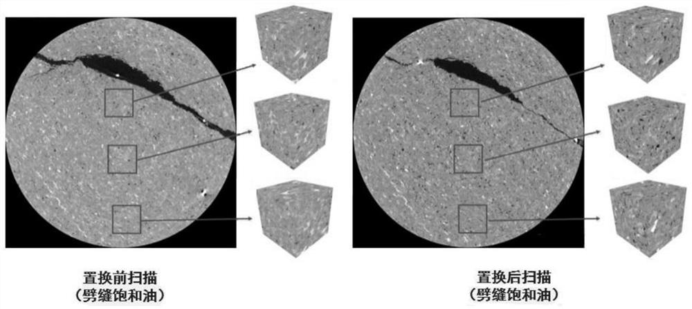
[0036] Step 1: Select the plunger core sample in the target area, and manually press it into cracks and install it into the CT holder;

[0037] Step 2: saturate the plunger core sample treated in step 1 with formation water, and use the formation water in the fractured core to displace the formation water to establish irreducible water saturation;

[0038] Step 3: For the plunger core sample saturated formation crude oil processed in step 2, measure the volume V of the original saturated crude oil under the experimental temperature and pressure conditions 0 ;

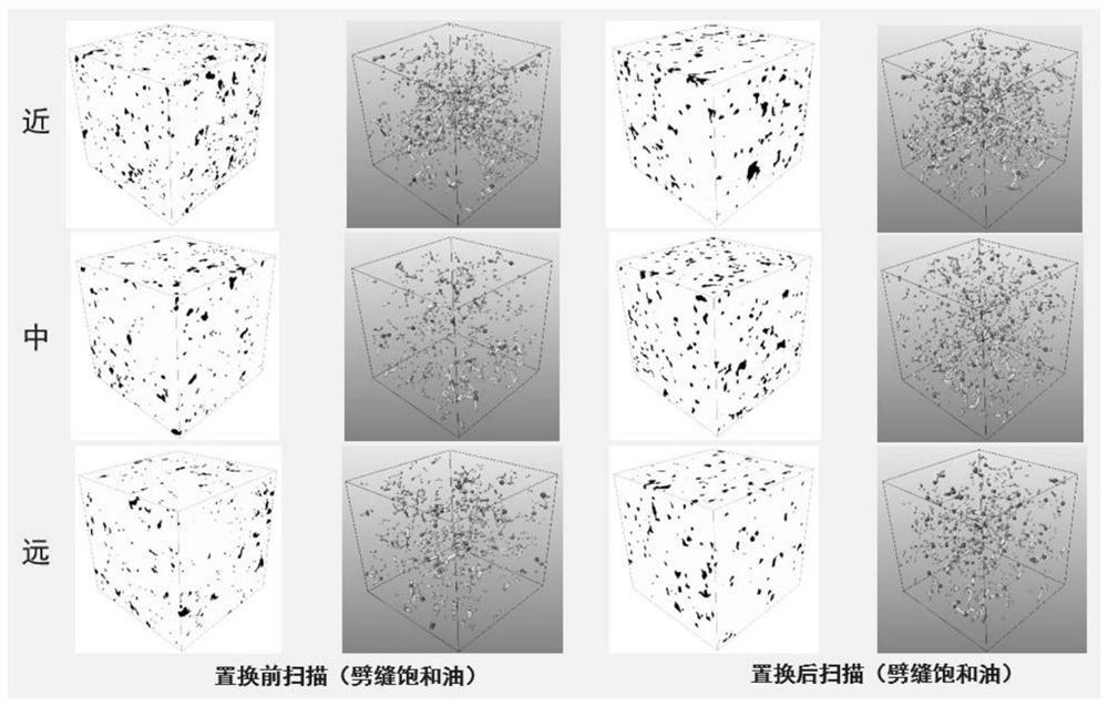
[0039] Step 4: Obtain the initial pore structure characteristics and fluid distribution characteristics of the plunger core sample processed in step 3 by CT scanning;

[0040] Step 5: Inject CO at preset pressure 2 Afterwards, CT scanning is performed, and at the same time, the wel...

Embodiment 2

[0048] A dry fracturing CO2 2 The difference from the first embodiment is that the experimental method of reservoir fluid replacement law is that in the second step, the method of saturating the plunger core sample treated in the first step with formation water is evacuated and pressurized.

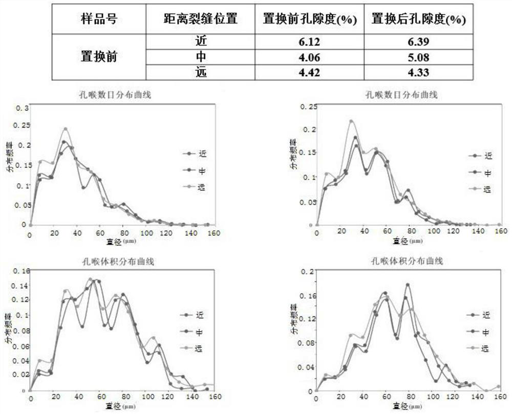
[0049] Further, the initial pore structure characteristics in Step 4 and Step 7 include pore size distribution and throat size distribution; fluid distribution characteristics include oil, gas, and water saturation in the pores.

[0050] Further, the setting of different scanning times in step 5 is set at equal intervals within the preset soaking time.

[0051] Further, the CO injected in the step five 2 99.999% pure.

[0052] Further, the calculation of replacement efficiency in step six of the step is calculated using the following formula to obtain

[0053]

[0054] Among them: E D is the replacement efficiency;

[0055] B 0 is the formation crude oil volume factor;

[0056] V ...

Embodiment 3

[0063] refer to Figure 1-Figure 3 As shown, a dry fracturing CO 2 Experimental method of replacement law with reservoir fluid,

[0064] Step 1: Select a plunger core sample in a target area, and manually press it into cracks and install it into the CT holder;

[0065] Step 2: saturate the plunger core sample treated in step 1 with formation water, and use the formation water in the fractured core to displace the formation water to establish irreducible water saturation;

[0066] Step 3: For the plunger core sample saturated formation crude oil processed in step 2, measure the volume V of the original saturated crude oil under the experimental temperature and pressure conditions 0 , V 0 =1.216mL;

[0067] Step 4: Obtain the initial pore structure characteristics and fluid distribution characteristics of the plunger core sample processed in step 3 through CT scanning; the pore throat size distribution is obtained as 0-158 μm, mainly distributed between 20-100 μm, and 5 mm a...


PUM


Abstract

The invention belongs to the technical field of oil well fracturing, and particularly relates to a CO2 and reservoir fluid replacement rule experimental method after dry fracturing soaking. The methodcomprises the following steps of selecting a plunger rock core sample in a target area, pressing the plunger rock core sample into a crack, putting the crack into a CT holder, saturating formation water for the treated plunger rock core sample, and displacing the formation water in the crack rock core; establishing irreducible water saturation, saturating stratum crude oil with the treated plunger core sample, measuring saturated oil quantity V<0>, acquiring an initial pore structure and fluid distribution characteristics of the treated plunger core sample, injecting CO2 according to preset pressure, scanning, soaking in a well, performing CT scanning for a set time within preset soaking time, performing flowback until soaking is finished, measuring the flow-back oil quantity V<1> and calculating the replacement efficiency; carrying out CT scanning to obtain a pore structure and fluid distribution characteristics of the fractured rock core after CO2 replacement; and comparing and analyzing the pore structure and the fluid distribution characteristics before and after CO2 injection to obtain the reservoir fluid replacement rule of the target area.

Description

technical field [0001] The invention belongs to the technical field of oil well fracturing development, in particular to a CO 2 Experimental method of displacement law with reservoir fluid. Background technique [0002] In the prior art, the fracturing is mainly completed through the hydraulic fracturing method mainly based on dialysis, and the fracturing is carried out by this method, and the main considerations are whether the fracturing is possible, whether the sand is carried, etc., and the replacement efficiency is not considered high and low. Using hydraulic fracturing, because water is insoluble in oil, the efficiency of flowback is poor, the supporting effect is not strong, and the development effect of crude oil is poor. Therefore, there is a need for a method that can improve the reservoir fluid displacement law and improve the crude oil development effect. Contents of the invention [0003] The invention provides a dry fracturing CO2 2 The experimental metho...

Claims


Application Information

Patent Timeline
Patent Type & Authority Applications(China)
IPC IPC(8): E21B43/16E21B43/26E21B47/00E21B49/00
CPCE21B43/164E21B43/26E21B47/00E21B49/00Y02P90/70
Inventor 夏玉磊王祖文张冕兰建平池晓明陶长州刘欢叶赛任斌欧阳伟平刘锦江杨敏
Owner BC P INC CHINA NAT PETROLEUM CORP
Why Eureka
Try Eureka