Shaft-mounted brake disc connecting device and vehicle adopting same

A connecting device and brake disc technology, applied in the direction of the brake disc, etc., can solve the problems of bolt failure, failure to improve the axial tilt of the bolt, and failure to effectively avoid shear force, etc., so as to avoid bolt failure and reduce driving safety accidents The effect of the risk

Pending Publication Date: 2021-03-09
CRRC CHANGZHOU TECH MARK IND CO LTD +1
View PDF13 Cites 4 Cited by
  • Summary
  • Abstract
  • Description
  • Claims
  • Application Information

AI Technical Summary

Problems solved by technology

The utility model patent with Chinese patent application No. 200820124337.3 discloses a wheel-mounted brake disc device. Although the sliding positioning pin between the brake disc and the wheel can protect the bolts from circumferential shear to a certain extent during the braking process shear force, but it cannot effectively avoid the shear force in the radial direction of the brake disc. Moreover, as the wear of the brake disc increases, if the bilateral brake discs have eccentric wear, wave wear, warping, etc., or due to clamping When the fault of the caliper causes uneven force on the brake discs on both sides, the force, temperature rise and deformation of the wheel-mounted brake discs on both sides of the wheel will be inconsistent during the braking process, which will easily make the bolts tilt along the axial direction and be subject to multiple Section shear action causes bolt failure
Compared with the 200820124337.3 wheel-mounted brake disc device in this patent, the bolts can avoid the radial shear force to a certain extent while being protected from the circumferential shear force, but it cannot improve the impact of the double-sided brake disc during braking. The axial inclination of the bolts caused by inconsistent force, temperature rise, and deformation, and the avoidance of failure caused by the multi-section shearing effect of the bolts

Method used


Image

  • Shaft-mounted brake disc connecting device and vehicle adopting same
  • Shaft-mounted brake disc connecting device and vehicle adopting same
  • Shaft-mounted brake disc connecting device and vehicle adopting same

Examples


Embodiment Construction

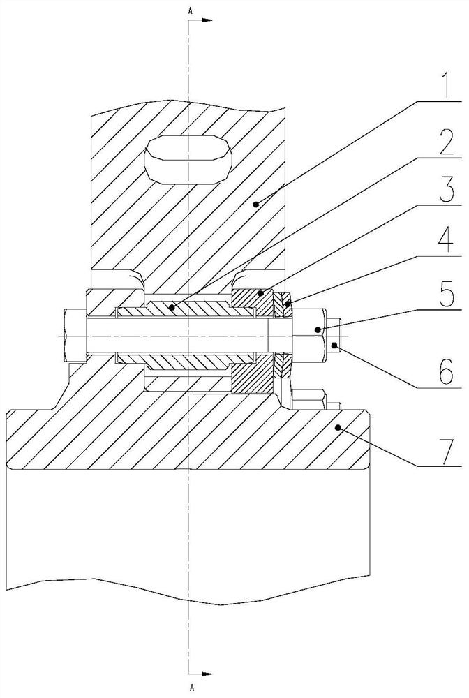
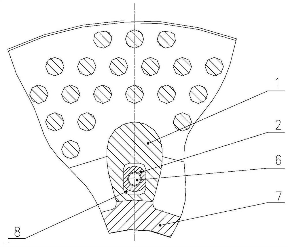
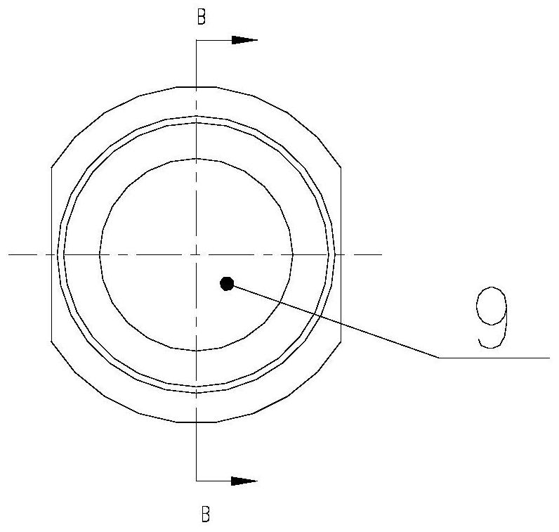
[0035] This embodiment provides a shaft brake disc connection device, such as Figure 1-8As shown, including the disc body 1, the hollow pin 2, the pressure plate 3, butterfly spacer 4, the locking nut 5, the bolt 6, and the hub 7. Each of the disk bodies 1 and the plate hub 7 have a connecting portion having a mounting hole on each of the connecting portions, and the pressure plate 3 also has a mounting hole such as a circumferential distribution. The mounting holes include bolt holes and hollow pin holes, and the plurality of hollow pin holes are arranged with bolt holes. The hollow pin holes 8 on the disk body 1 are a lumbar through hole concentric with the bolt holes on the disc connection, and the hollow pin holes on the press plate 3 and the hub 7 are inserted with the bolt holes. The hollow pin 2 is a concentric stepped structure, and the center has through through holes, and both ends are cylindrical structures, and the central part is a lumbar structure.

[0036] In this e...


PUM


Abstract

The invention provides a shaft-mounted brake disc connecting device. A disc body and a disc hub are both provided with connecting parts which are the same in number and distributed in the same circumference; the connecting parts are provided with mounting holes; pressing plate connecting parts are provided with pressing plate mounting holes which are consistent with the mounting holes in the connecting parts of the disc body and disc hub in position and distributed in the same circumference; the mounting holes of the connecting parts of the disc body and the disc hub are correspondingly coincided; hollow pin connecting parts are inserted into the mounting holes; the pressing plate connecting parts are attached to the outer sides of the connecting parts of the disc body; the pressing platemounting holes of the hollow pin connecting parts are connected onto end columnar structures of the hollow pin connecting parts in a sleeving mode; and the connecting parts of the disc body are fixedonto the connecting parts of the disc hub through locking nut connecting parts. According to the shaft-mounted brake disc connecting device provided by the invention, by additionally arranging hollowpins with special structures, in the application process of a brake disc, circumferential rotation and dislocation do not occur among the disc body, a pressing plate and the disc hub, and meanwhile, when the disc body, the pressing plate and the disc hub are deformed or displaced in the radial direction due to temperature increase or accidental impact during braking of the brake disc, the risk ofdriving safety accidents caused by bolt breakage is reduced.

Description

Technical field [0001] The present invention relates to a train shaft manda disc connection structure, in particular a shaft brake disc connection device, and a vehicle employing the device, belonging to the technical field of train brakes. Background technique [0002] Safety and high speed are two major goals pursued by urban rail transit systems. Whether the rail transit system can operate safely, it is largely, depending on its performance of its brake system. After decades of R & D, experiments and applications show that the frictional performance of the disc-shaped brakes is stable, the absorption energy is large, and the heat dissipation performance is good, and more useful in the basic brakes of the rail transit vehicle. At present, the speed of 350 kilometers China Standard EMU is currently developing 250 kilometers. China Standard EMUs in China Standard EMUs, 160 kilometers of dynamic concentrated EMUs, all, in which the motor vehicle uses a wheel-based brake device. Th...

Claims


Application Information

Patent Timeline
Patent Type & Authority Applications(China)
IPC IPC(8): F16D65/12
CPCF16D65/12
Inventor 张海锋方明刚金文伟杜利清冯昆
Owner CRRC CHANGZHOU TECH MARK IND CO LTD
Why Eureka
Try Eureka