
Adjustable groove depth measuring device and measuring method

A groove depth, measuring device technology, applied in the field of parts processing and measuring, can solve the problems of increasing the measurement work cost, disadvantageous measurement efficiency, measurement error, etc., and achieve the effects of convenient adjustment and locking, improved measurement efficiency, and convenient and simple operation.

Active Publication Date: 2021-03-09
天津旗领机电科技有限公司
View PDF4 Cites 0 Cited by
  • Summary
  • Abstract
  • Description
  • Claims
  • Application Information

AI Technical Summary

Problems solved by technology

On the one hand, this method will cause measurement errors due to the introduction of transitional benchmarks; on the other hand, due to the precision and structural limitations of measuring instruments, various special measuring devices or instruments are often equipped according to different parts, which not only increases the cost of measuring work, And it is not conducive to the improvement of measurement efficiency

Method used


Image

  • Adjustable groove depth measuring device and measuring method
  • Adjustable groove depth measuring device and measuring method
  • Adjustable groove depth measuring device and measuring method

Examples


Embodiment Construction

[0036] The present invention will be described in further detail below in conjunction with the drawings and specific examples. The following examples are only descriptive, not restrictive, and cannot limit the protection scope of the present invention.

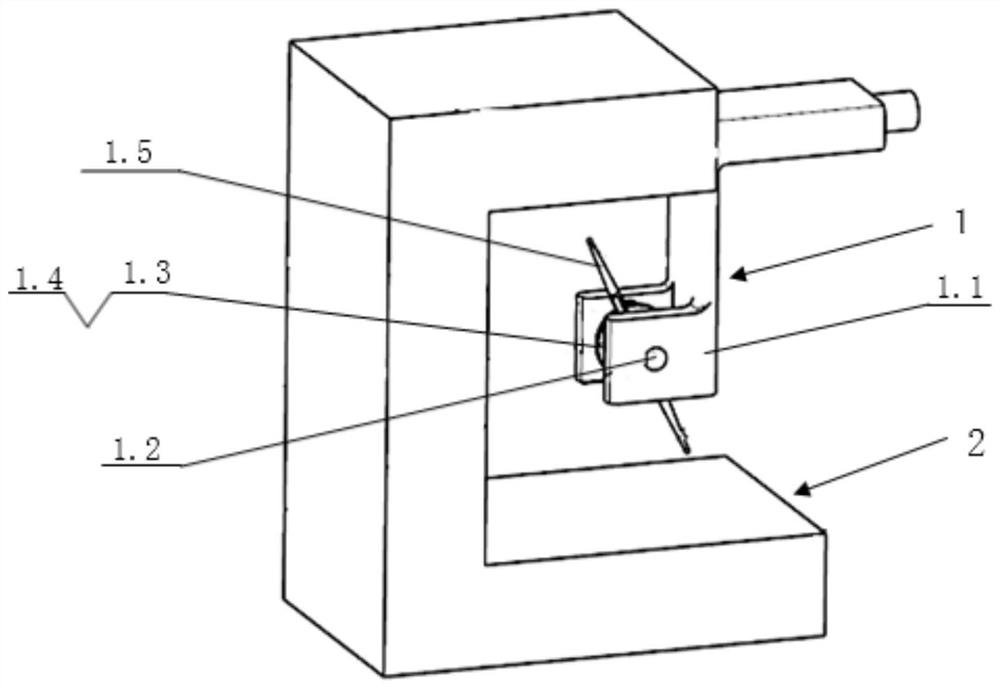
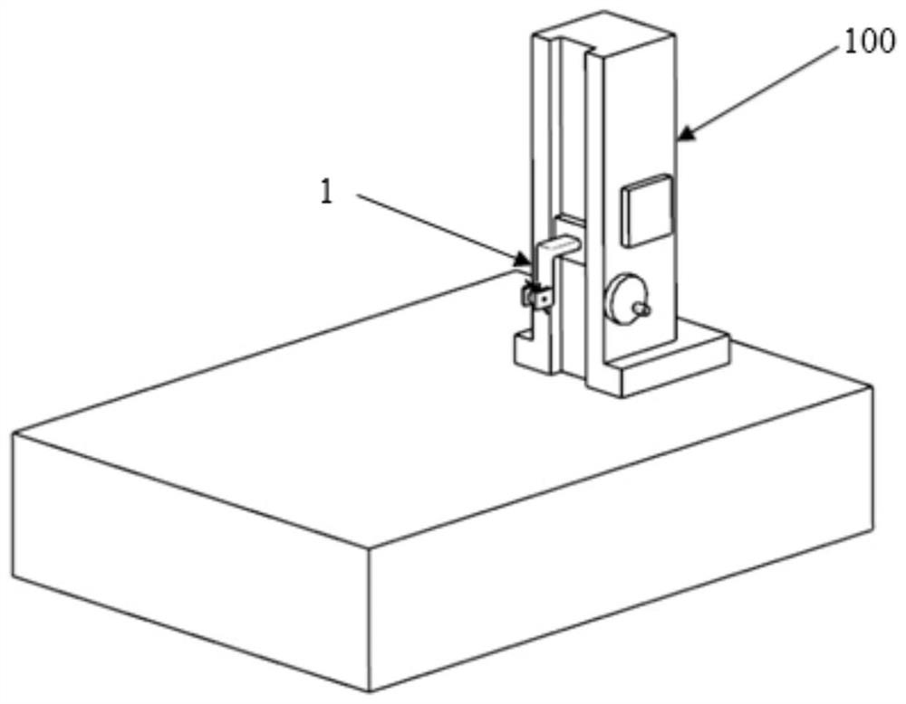
[0037] An adjustable groove depth measuring device, see Figure 1-6 , the invention point is: including a measuring head assembly 1 and a calibration gauge block 2 .

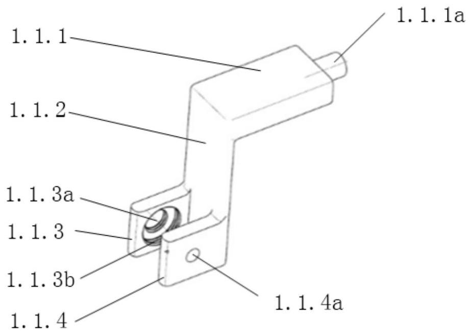
[0038] The measuring head assembly includes a frame 1.1, an insert 1.3, an adjustment block 1.4, a compression screw 1.2 and two measuring pins 1.5. The frame is composed of a tail end 1.1.1, a measuring end and a connecting arm 1.1.2 between them, the tail end is provided with a pin shaft 1.1.1a cooperating with the measuring instrument 100, and the measuring end is composed of two parallel The left and right sides of the support plate are formed, and the accommodation groove is formed between the two sides of the support plate, and the threaded hole 1.1.3a fo...


PUM


Abstract

The invention relates to an adjustable groove depth measuring device and a measuring method. The device comprises a measuring head assembly and a calibration gauge block. The measuring head assembly comprises a rack, an insert, an adjusting block, a pressing screw and two measuring pins. An accommodating groove is formed between two lateral supporting plates at the measuring end of the rack, the insert and the adjusting block are arranged in the accommodating groove, meshed teeth are arranged on the opposite surfaces of the insert and the adjusting block, two coaxial measuring pin mounting screw holes are formed in the side wall of the adjusting block, and the two measuring pins are respectively connected to the positions of the two measuring pin mounting holes through threads; the pressing screw penetrates through the left lateral supporting plate, the insert, the adjusting block and the right lateral supporting plate and is in threaded connection with the left lateral supporting plate and the adjusting block in the opposite rotating directions, a calibration groove with an opening in one side is formed in the calibration gauge block, and the distance between the upper calibrationface and the lower calibration face of the calibration groove is the calibration height of the calibration gauge block. The interference part of the part structure on the measuring instrument can beavoided, so that the size of the to-be-measured part of the part can be directly measured.

Description

technical field [0001] The invention belongs to the technical field of part processing and measurement, and in particular relates to an adjustable groove depth measuring device and a measuring method. Background technique [0002] At present, in order to obtain the depth dimension of the groove of the part, the engineering site usually uses the transition datum to measure the depth of the groove of the part multiple times and perform additional calculations. On the one hand, this method will cause measurement errors due to the introduction of transitional benchmarks; on the other hand, due to the precision and structural limitations of measuring instruments, various special measuring devices or instruments are often equipped according to different parts, which not only increases the cost of measuring work, And it is not conducive to the improvement of measurement efficiency. Contents of the invention [0003] The purpose of the present invention is to overcome the deficie...

Claims


Application Information

Patent Timeline
Patent Type & Authority Applications(China)
IPC IPC(8): G01B21/18
CPCG01B21/18G01B21/042
Inventor 张磊常乐韩研研李红杨瑞军余正权王昭
Owner 天津旗领机电科技有限公司
Learn More