Sludge drying device and using method thereof

A sludge drying and sludge technology, applied in the direction of dehydration/drying/concentrated sludge treatment, etc., can solve the problems of high viscosity, easy to block ventilation holes, high sludge viscosity, etc., and improve the sludge reduction ratio , speed up the drying process, increase the effect of contact frequency

Pending Publication Date: 2021-03-12
广州正晟科技有限公司
View PDF0 Cites 0 Cited by
  • Summary
  • Abstract
  • Description
  • Claims
  • Application Information

AI Technical Summary

Problems solved by technology

However, since the heat transfer is realized through the flow of high-temperature hot oil or hot steam in the hollow shaft and the stirring blade, the stirring blade is easy to wear and break, and the treated sludge has a high water content and a high viscosity
This not only leads to high failure rate and high energy consumption of sludge treatment equipment, but also very low sludge drying efficiency
The direct drying equipment makes the hot air directly act on the sludge to evaporate the moisture in the sludge. Although the heat transfer efficiency is improved, due to the high viscosity of the sludge, it is easy to block the ventilation holes, which not only affects the stability of the drying process , and because of the uneven drying of sludge, it is difficult to achieve sludge reduction, and the drying efficiency of sludge is low, which makes it impossible to dry large quantities of sludge

Method used


Image

  • Sludge drying device and using method thereof
  • Sludge drying device and using method thereof
  • Sludge drying device and using method thereof

Examples


Embodiment Construction

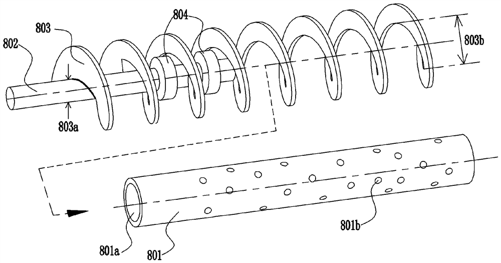
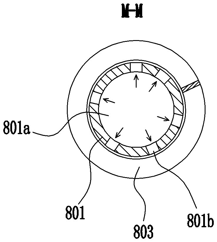
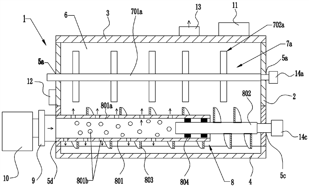
[0042] figure 1 An embodiment of a fluid conveying arrangement according to the application for a sludge treatment plant is shown in a partially cutaway perspective view. figure 2 Shown in cross section figure 1 The structure of the fluid transport assembly at the M-M position, while image 3 Shown in cross section figure 1 The structure of the fluid delivery assembly at the N-N position with the rotation axis. As shown, the fluid delivery assembly S includes a fluid delivery tube or barrel 801 , a rotating shaft 802 and a screw 803 . The screw 803 can also be called a screw or a screw blade, and one end of the screw 803 is fixedly connected to the rotating shaft 802, and the other end is sleeved on the delivery pipe 801, wherein the rotating shaft 802 is connected to the part of the screw 803 Located outside the fluid delivery tube 801, another part of the rotating shaft 802 is rotatably disposed inside the fluid delivery tube 801, so that most of the screw 803 can rotat...


PUM


Abstract

The invention provides an axial air supply type sludge drying device, which comprises: a shell, wherein a drying chamber is arranged in the shell, and is provided with a sludge feeding port, a tail gas exhaust port and a sludge discharging port; a turning device provided with a turning assembly; and an axial air supply assembly comprising an air supply pipe with an axial hole and a vent hole, a spiral piece with shaft holes with different inner diameters and a rotating shaft, wherein the spiral piece is fixedly connected with the rotating shaft through a part of the shaft holes, after the rotating shaft and the spiral piece are assembled on the air supply pipe, one part of the rotating shaft is rotatably arranged in the axial hole of the air supply pipe, and the other part of the spiral piece is rotatably sleeved on the air supply pipe, the axial air supply assembly is arranged on the lower portion of the drying chamber of the shell, the turning device is located above the axial air supply assembly, and a discharging port in the end wall of the shell is located between the turning device and the axial air supply assembly. The invention also provides a method for drying sludge by using the axial air supply type sludge drying device.

Description

technical field [0001] The present application relates to the field of sludge drying, in particular to an axial air-supply type sludge drying device for sludge treatment and a method for drying sludge by using the axial air-supply type sludge drying device. Background technique [0002] At present, the common sludge treatment devices are indirect and direct drying equipment. The indirect drying equipment is to deliver steam, hot oil or hot water to the hollow shaft and stirring blades running in the drying chamber to heat up the shaft and stirring blades, and then use the heat conduction hollow shaft and stirring blades to transfer heat to the drying chamber. The wet sludge in the room evaporates the moisture in the sludge and makes it dry gradually. However, since the heat transfer is realized through the flow of high-temperature hot oil or hot steam in the hollow shaft and the stirring blade, the stirring blade is easy to wear and break, and the treated sludge has a high ...

Claims


Application Information

Patent Timeline
Patent Type & Authority Applications(China)
IPC IPC(8): C02F11/13
CPCC02F11/13
Inventor 谭玮
Owner 广州正晟科技有限公司
Why Eureka
Try Eureka