
Drying device for drying sludge by using flue gas

A drying device and sludge technology, applied in the direction of dewatering/drying/concentrating sludge treatment, etc., can solve the problems of waste of heat energy, no land available, a lot of heat energy, etc., to avoid "fluidity" obstacles and prevent dry agglomeration. , The effect of preventing sludge adhesion

Inactive Publication Date: 2012-05-23
JIANGDU SUNENG ELECTRICAL EQUIP
View PDF0 Cites 75 Cited by
  • Summary
  • Abstract
  • Description
  • Claims
  • Application Information

AI Technical Summary

Problems solved by technology

The traditional sludge treatment method is landfilling, which requires considerable expenses during the landfilling process, and there is no guarantee that it will not cause secondary pollution.
Second, the method of roasting is even more unscientific, and roasting requires a lot of heat energy, which does not meet the purpose of energy saving at all, and also causes secondary pollution to the surrounding environment
The temperature of the hot exhaust gas discharged from the boiler reaches 140-180°C; it is directly discharged into the atmosphere, on the one hand, a lot of heat energy is wasted, and on the other hand, the particles in the hot exhaust gas will cause great pollution to the environment
[0004] Sewage treatment will produce a lot of organic sludge, which is very troublesome to deal with. If it is directly landfilled, land resources will be tight and there will be no land available.
If it is dried and then landfilled, the drying process requires a large cost

Method used


Image

  • Drying device for drying sludge by using flue gas
  • Drying device for drying sludge by using flue gas
  • Drying device for drying sludge by using flue gas

Examples


Embodiment Construction

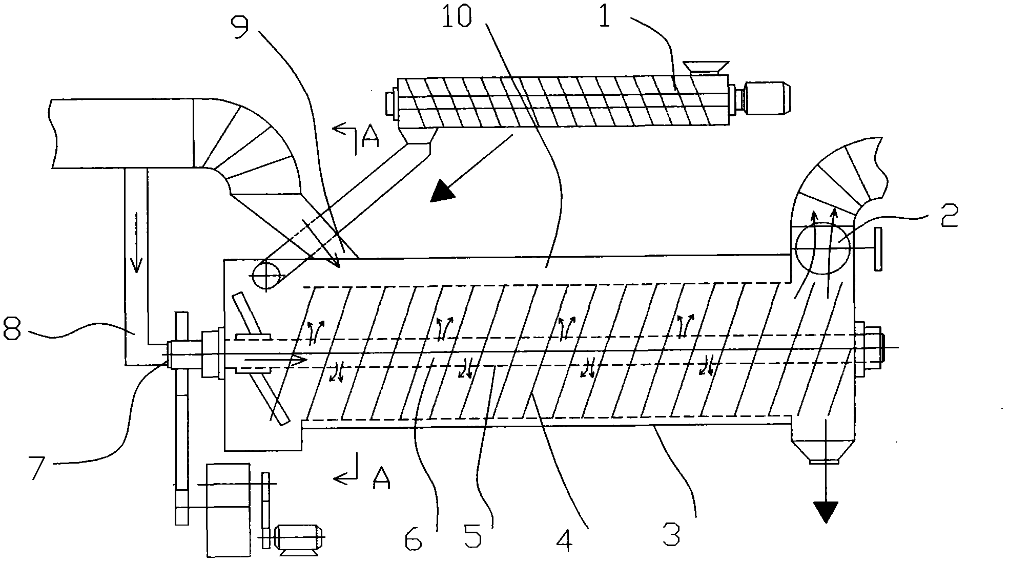
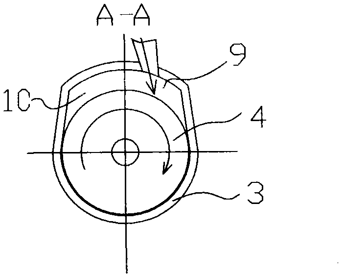
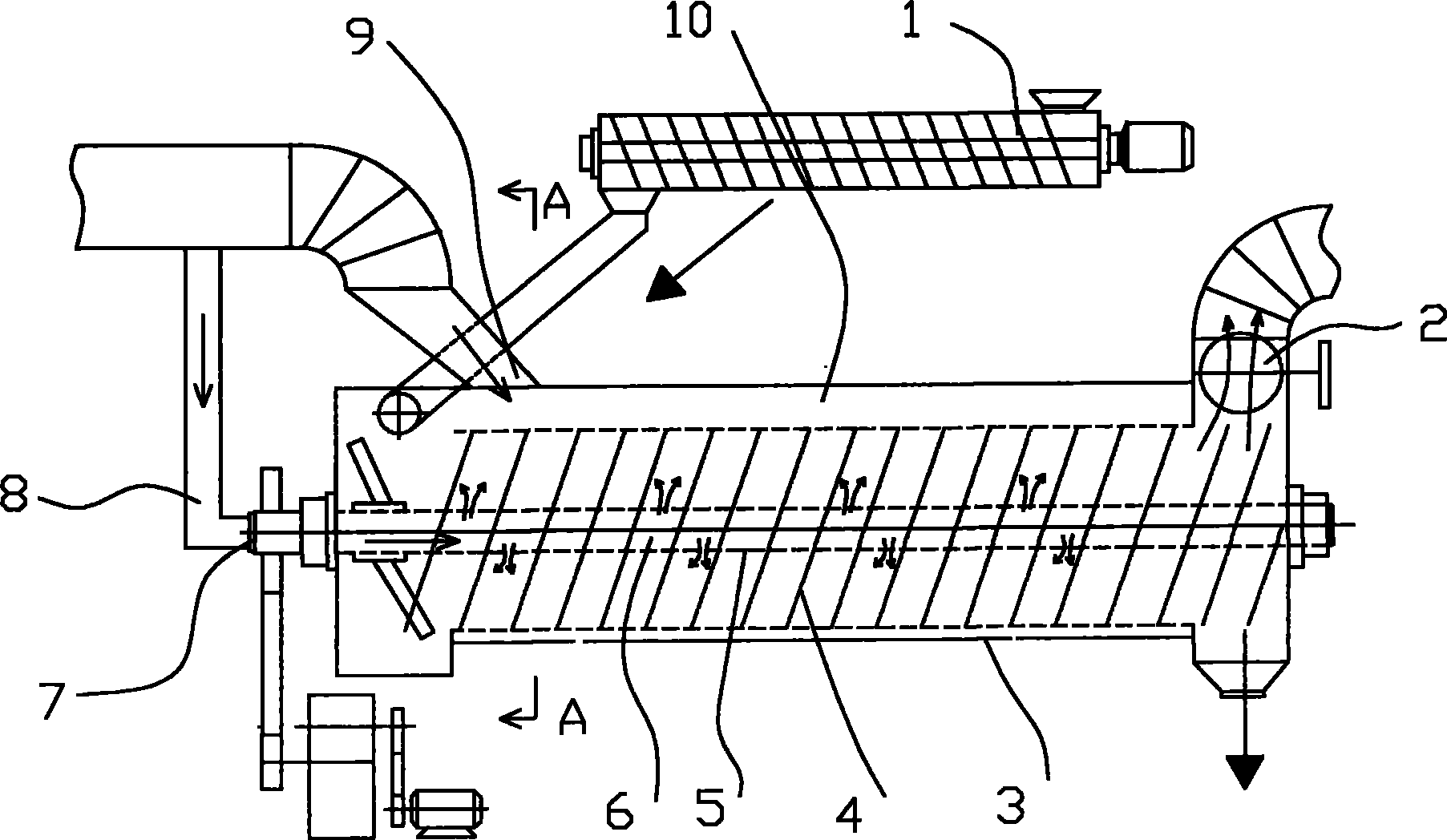
[0015] The present invention as figure 1 As shown: it includes a flue gas conveying pipeline and a sludge conveying device 1, and the drying device includes a cylinder body 3, a hollow shaft 6, a feeding screw 4 and an air inlet 8 connected to the flue gas conveying pipeline;

[0016] One end of the cylinder body 3 is connected to the sludge conveying device 1, the upper part of the other end of the cylinder body 3 is provided with an air outlet 2, and the lower part is provided with a mud outlet;

[0017] The hollow shaft 6 is movably arranged in the middle of the cylinder body 3, coaxial with the cylinder body 3; the feeding screw 4 is fixedly connected to the hollow shaft 6; The shaft head at one end of the mud conveying device 1 protrudes from the cylinder body 3, and is connected with the air inlet one 8 through the rotary joint 7; the hollow shaft 6 is provided with a number of air holes 5 facing the surface of the conveying screw 4 in the airflow direction.

[0018] As...


PUM

PropertyMeasurementUnit
heating valueaaaaaaaaaa

Abstract

The invention provides a drying device for drying sludge by using flue gas. The invention relates to an environment-friendly treatment device, in particular to a drying device for dynamically drying wet sludge by using high-temperature (120-200 DEG C) flue gas. The drying device comprises a flue gas conveying pipeline and a sludge conveying device. The drying device is characterized by comprising a cylinder body, a hollow shaft, a material conveying spiral and a gas inlet duct communicated with the flue gas conveying pipeline. Aiming at the problems, the invention provides the drying device for online drying wet sludge by using flue gas so as to greatly improve treatment efficiency and reduce environmental pollution.

Description

technical field [0001] The invention relates to environmental protection treatment equipment, in particular to a drying device for dynamically drying wet sludge by using flue gas at high temperature (120-200°C). Background technique [0002] When people treat sewage, they often ignore the treatment of sludge generated after sewage treatment, so the sludge treatment equipment and technology are relatively lagging behind. The traditional sludge treatment method is landfilling, which requires a considerable amount of expense, and there is no guarantee that it will not cause secondary pollution. The second is that the method of roasting is even more unscientific, and roasting requires a lot of heat energy, which does not meet the purpose of energy saving at all, and also causes secondary pollution to the surrounding environment. Due to the unscientific treatment of sludge, incidents of secondary pollution continue to occur, which has been plagued by enterprises and related depa...

Claims


Application Information

Patent Timeline
Patent Type & Authority Applications(China)
IPC IPC(8): C02F11/12
Inventor 徐开金
Owner JIANGDU SUNENG ELECTRICAL EQUIP
Learn More