Tool and method for sleeving rigid thermal protection layer on non-closed equal-diameter revolving body cabin section

A heat protection layer and non-enclosed technology, applied in the direction of connecting components, material gluing, weight reduction, etc., can solve the problems of high profile requirements, difficulty, and low efficiency of the aircraft, so as to avoid interference and damage the cabin and ensure the profile , highly operable effect

Active Publication Date: 2021-03-12
AEROSPACE INST OF ADVANCED MATERIALS & PROCESSING TECH
View PDF5 Cites 4 Cited by
  • Summary
  • Abstract
  • Description
  • Claims
  • Application Information

AI Technical Summary

Problems solved by technology

The problem with this method is that, on the one hand, there will inevitably be gaps at the joints of the heat protection materials, and more heat will be transferred to the interior of the aircraft, which will bring hidden dangers to the normal operation of components; on the other hand, when bonding Each piece of thermal protection material needs to be aligned and positioned, and has high requirements on the profile of the aircraft, and the assembly process is complex, difficult, and inefficient
Although this method avoids too many joints in the block scheme, there are still some problems: the preparation of the thermal protection layer and the preparation of the cold structure of the cabin cannot be carried out in parallel, and the thermal protection must be carried out after the processing of the cold structure is completed. In addition, when the thermal protection layer is prepared, the cabin section will experience temperature and pressure changes with the glue, and there is a certain risk. Once the cabin section is damaged, it will seriously affect the task progress of the product.
[0006] However, the non-enclosed equal-diameter revolving body section generally has a "C"-shaped cross section, and is generally made of machined or welded metal material. When welding is formed, the contour is difficult to guarantee, and there is a risk of out-of-tolerance, which may even cause The product is damaged, and for the cabin section of the equal-diameter rotary body, it is easy to scrape the glue between the thermal protection layer and the cabin during the socketing. How to efficiently and accurately connect the thermal protection layer to the non-closed equal-diameter rotary cabin section is an urgent problem to be solved

Method used


Image

  • Tool and method for sleeving rigid thermal protection layer on non-closed equal-diameter revolving body cabin section
  • Tool and method for sleeving rigid thermal protection layer on non-closed equal-diameter revolving body cabin section
  • Tool and method for sleeving rigid thermal protection layer on non-closed equal-diameter revolving body cabin section

Examples


Embodiment 1

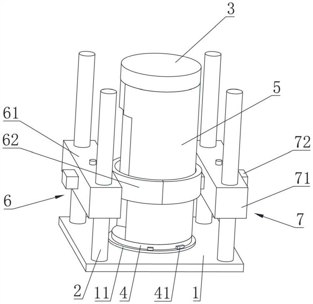
[0064] see figure 1 As shown, the rigid heat protection layer provided by the embodiment of the present invention is sleeved on the non-enclosed isometric rotary body cabin section, including a bottom plate 1, four columns 2, a front extension 3, a rear extension 4 and at least one sliding mold , wherein, one end of the column 2 is vertically connected to the bottom plate 1, the front extension 3 and the rear extension 4 are respectively installed at the front end and the rear end of the cabin section 5, and the axial distance between the front end and the rear end of the cabin section 5 is extended Size, so that the axial margin of the heat protection layer is also better installed and fixed, to ensure the quality of the heat protection layer at the front edge and the rear end edge. The front extension 3 and the rear extension 4 generally adopt a cylindrical structure with the same diameter as the cabin section.

[0065] The sliding mold includes a first side mold 6 and a se...

Embodiment 2

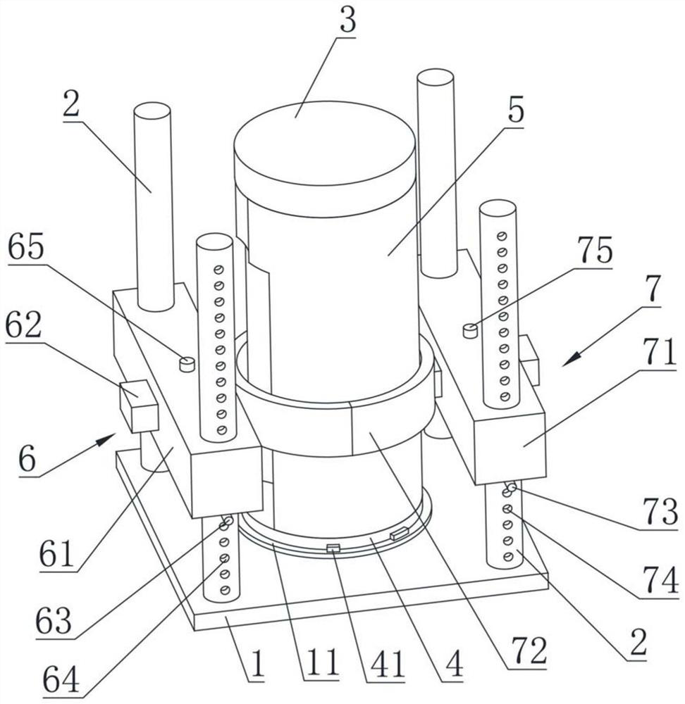
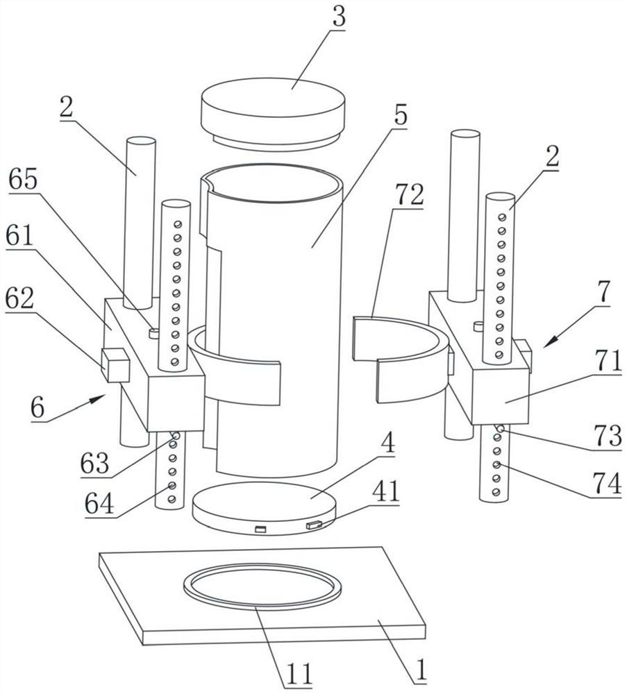
[0076] see figure 2 and image 3 As shown, the second embodiment is basically the same as the first embodiment, and the similarities will not be repeated. The difference is that at least one column 2 for installing the first axial sliding part 61 is provided with multiple The first adjustment hole 64, a plurality of the first adjustment holes 64 are arranged at intervals along the axial direction of the column 2, and the first adjustment pin 63 cooperates with the first adjustment hole 64 to fix the first side mold 6 in the The upper position of the column 2 in the axial direction.

[0077] At least one column 2 for installing the second axial sliding part 71 is provided with a plurality of second adjustment holes 74, and the plurality of second adjustment holes 74 are arranged at intervals along the axial direction of the column 2, The position of the second side mold 7 in the axial direction of the column 2 is fixed by the second adjustment pin 73 cooperating with the sec...

Embodiment 3

[0081] The third embodiment is an improvement on the basis of any one of the first or second embodiments, and the similarities will not be repeated. The axial direction of the column 2 is installed on the column 2. By adjusting the position of multiple sliding molds, the segmental positioning of the heat protection layer can be realized, which can avoid the interference position, avoid interference and damage the cabin, and maximize the Ensure the contour of the heat protection layer after socketing.

[0082] see Figure 4 As shown, a tooling structure is schematically shown, including two sliding molds. Of course, in some other embodiments, the number of sliding molds can also be adjusted as required, for example, three sliding molds, four sliding molds.


PUM


Abstract

The invention relates to the technical field of thermal protection materials, in particular to a tool and method for sleeving a rigid thermal protection layer on a non-closed equal-diameter revolvingbody cabin section. The tool comprises a bottom plate, a front extension part, a rear extension part, a plurality of stand columns and at least one sliding die; one end of each stand column is perpendicularly connected to the bottom plate; the front extension part and the rear extension part are installed at the front end and the rear end of the cabin section correspondingly; the sliding dies areinstalled on the stand columns, can move in the axial direction of the stand columns and can be adjusted to a certain degree in the radial direction; the overall profile tolerance of the thermal protection layer can be guaranteed within a certain range, an interference area can be avoided, and therefore the cabin body or the thermal protection layer is prevented from being damaged; and in addition, in the process of sleeving the thermal protection layer, the thermal protection layer can be efficiently and accurately connected to the non-closed equal-diameter revolving body cabin section in a sleeving mode without an additional positioning tool, the structure is simple, and operation is convenient. The method uses the tool for auxiliary installation, is easy and convenient to implement andhigh in operability, and suitable for batch production.

Description

technical field [0001] The invention relates to the technical field of heat protection materials, in particular to a tool and a method for a rigid heat protection layer to be sleeved on a non-enclosed equal-diameter revolving cabin section. Background technique [0002] When a hypersonic vehicle cruises at high speed for a long time in the atmosphere, the surface will be subjected to more severe thermal load and airflow erosion. [0003] The heat insulation scheme of the aircraft in the early stage is mainly to prepare heat protection materials in blocks, and then bond them to the surface of the aircraft piece by piece. The problem with this method is that, on the one hand, there will inevitably be gaps at the joints of the heat protection materials, and more heat will be transferred to the interior of the aircraft, which will bring hidden dangers to the normal operation of components; on the other hand, when bonding Each piece of thermal protection material needs to be ali...

Claims


Application Information

Patent Timeline
Patent Type & Authority Applications(China)
IPC IPC(8): F16B11/00
CPCF16B11/006Y02T50/40
Inventor 孙阔李文静杨洁颖宋寒郭慧苏力军柳晓辉
Owner AEROSPACE INST OF ADVANCED MATERIALS & PROCESSING TECH
Why Eureka
Try Eureka