Supercharge Your Innovation With Domain-Expert AI Agents!

Automatic cutting mechanism

An automatic cutting knife technology, which is applied in metal processing and other directions, can solve the problems that the distance of the cutting knife cannot be adjusted, and the material is easy to stick to the cutting knife, so as to achieve long working hours, avoid affecting work, and improve work efficiency.

Pending Publication Date: 2021-03-16
弘升智造(天津)科技有限公司
View PDF0 Cites 0 Cited by
  • Summary
  • Abstract
  • Description
  • Claims
  • Application Information

AI Technical Summary

Problems solved by technology

[0003] The purpose of the present invention is to provide an automatic material cutting mechanism to solve the problem that the existing cutting equipment proposed in the above-mentioned background technology cannot adjust the distance between the cutting knives and when the cutting knives cut viscous thick material, the material is very The problem of easy sticking to the cutting knife

Method used


Image

  • Automatic cutting mechanism
  • Automatic cutting mechanism
  • Automatic cutting mechanism

Examples


Embodiment

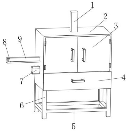
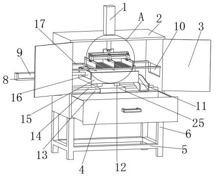
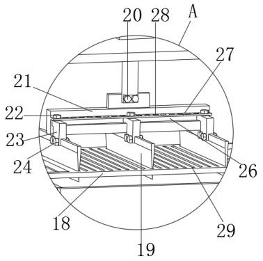
[0018] Example: see Figure 1-Figure 3 , the present invention provides an automatic material cutting mechanism, comprising a cutting box 2, the outer wall of the cutting box 2 is connected with a double door 3 through a hinge, the top of the cutting box 2 is fixedly installed with a first telescopic cylinder 1, the first telescopic cylinder 1 The output end of the output end extends to the inside of the cutting box 2, and the first mounting seat 21 is threaded through the first bolt 20. The outer wall of the first mounting seat 21 is provided with a chute 26, and the chute 26 on the outer wall of the first mounting seat 21 A plurality of second mounts 23 are installed, and the bottoms of the second mounts 23 are threadedly connected with a cutting knife 19 by second bolts 24, and the outer wall of the first mount 21 is fixedly connected to the limit plate 27 at the top of the chute 26, The limiting plate 27 is provided with a plurality of threaded holes 28 from top to bottom,...


PUM


Abstract

The invention relates to the technical field of automatic cutting, in particular to an automatic cutting mechanism. The automatic cutting mechanism comprises a cutting box, wherein a first telescopicair cylinder is installed in the cutting box, the output end of the first telescopic air cylinder extends to the cutting box, a first bolt is connected with a first installation base, a sliding grooveis formed in the first installation base, and second installation bases are installed in the sliding groove. The second installation bases are connected with cutting knives through second bolts, thefirst installation base is connected with a limiting plate, the limiting plate is provided with threaded holes, the threaded holes are provided with third bolts, the third bolts are connected with thesecond installation bases, the cutting box is provided with a scraping plate, and the cutting knives penetrate through the scraping plate. The second installation bases slide in the sliding groove ofthe first installation base, the third bolts on the limiting plate penetrate through the threaded holes to fix the limiting plate, the distance between the cutting knives can be adjusted, then materials with different widths can be cut out, then the materials adhering to the cutting knives can be scraped off through the scraping plate, the manual treatment cost is reduced, and the working efficiency is improved.

Description

technical field [0001] The invention relates to the technical field of automatic material cutting, in particular to an automatic material cutting mechanism. Background technique [0002] Thick material is a kind of material that is easy to deform after being stressed. Thick material will be processed by multiple processing equipment before use. Cutting is one of the processes. The existing cutting equipment cannot adjust the distance between the cutting knives. , so that the cutting width is fixed, and it is only suitable for segmental cutting of certain fixed thick materials. At the same time, when cutting thick materials, because the cutting knife is cutting sticky thick materials, the materials are easy to stick to the cutting On the knife, manual processing is required, which increases labor costs and greatly reduces production efficiency. Contents of the invention [0003] The purpose of the present invention is to provide an automatic material cutting mechanism to s...

Claims


Application Information

Patent Timeline
Patent Type & Authority Applications(China)
IPC IPC(8): B26D1/09B26D7/08B26D7/26
CPCB26D1/09B26D7/088B26D7/2614B26D7/2628
Inventor 常亚军
Owner 弘升智造(天津)科技有限公司
Features
  • R&D
  • Intellectual Property
  • Life Sciences
  • Materials
  • Tech Scout
  • Unparalleled Data Quality
  • Higher Quality Content
  • 60% Fewer Hallucinations
Learn More