On-site concrete pipe cutting equipment and using method thereof

A concrete and pipe technology, applied in the direction of stone processing tools, stone processing equipment, work accessories, etc., can solve the problems of low work efficiency, low cutting efficiency, poor cutting effect, etc., achieve uniform cutting, convenient movement, and reduce labor intensity Effect

Inactive Publication Date: 2021-03-16
BEIJING URBAN CONSTR DESIGN & DEV GRP CO
View PDF10 Cites 4 Cited by
  • Summary
  • Abstract
  • Description
  • Claims
  • Application Information

AI Technical Summary

Problems solved by technology

Concrete pipes have achieved standardized production in the process of production and processing, but in the process of use, due to the complex geological conditions, the concrete pipe piles of standardized sizes often cannot meet the construction needs, and the concrete pipe piles need to be cut on site to meet the design requirements, but The existing cutting equipment is mainly hand-held, which makes the operator labor-intensive and low-efficiency. However, for larger concrete pipes, the hand-held cutting equipment has low cutting efficiency and poor cutting effect. It is inconvenient to cut in different positions

Method used


Image

  • On-site concrete pipe cutting equipment and using method thereof
  • On-site concrete pipe cutting equipment and using method thereof
  • On-site concrete pipe cutting equipment and using method thereof

Examples


Embodiment Construction

[0034] The technical solutions of the present invention will be clearly and completely described below in conjunction with the embodiments. Apparently, the described embodiments are only some of the embodiments of the present invention, not all of them. Based on the embodiments of the present invention, all other embodiments obtained by persons of ordinary skill in the art without creative efforts fall within the protection scope of the present invention.

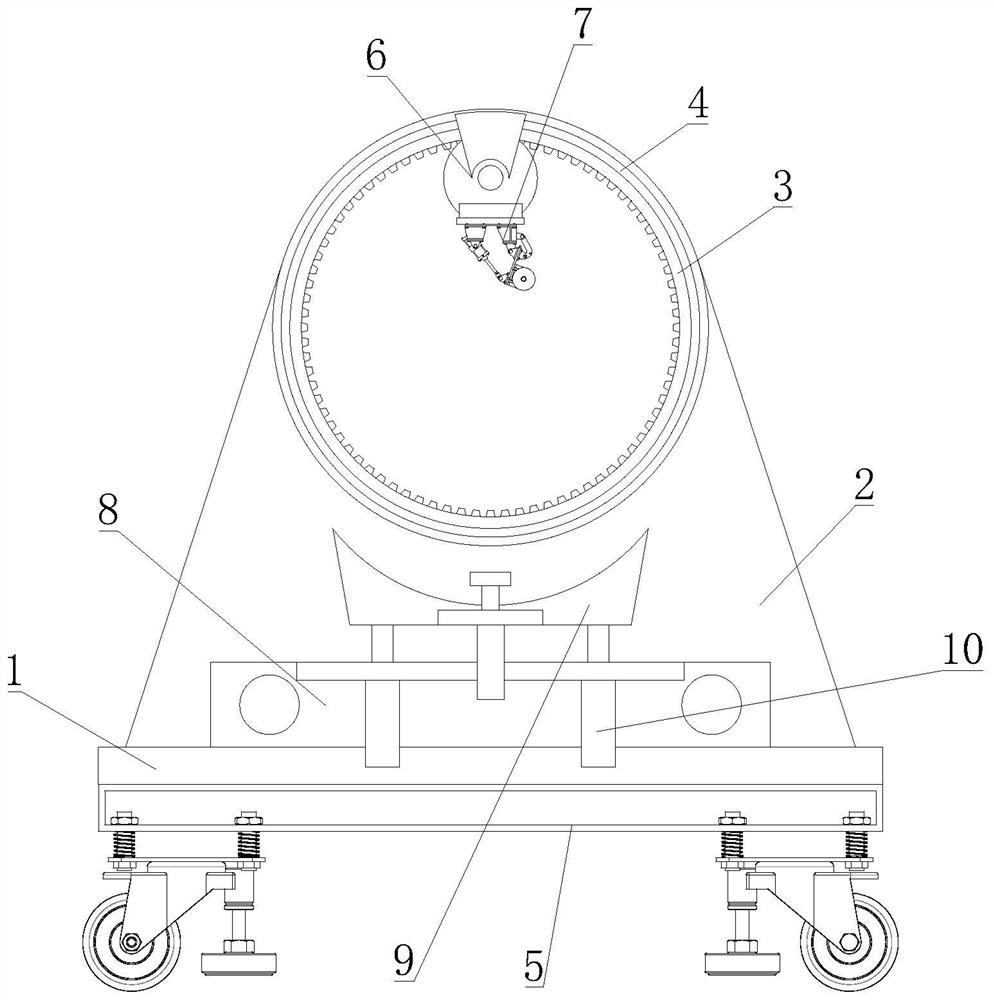
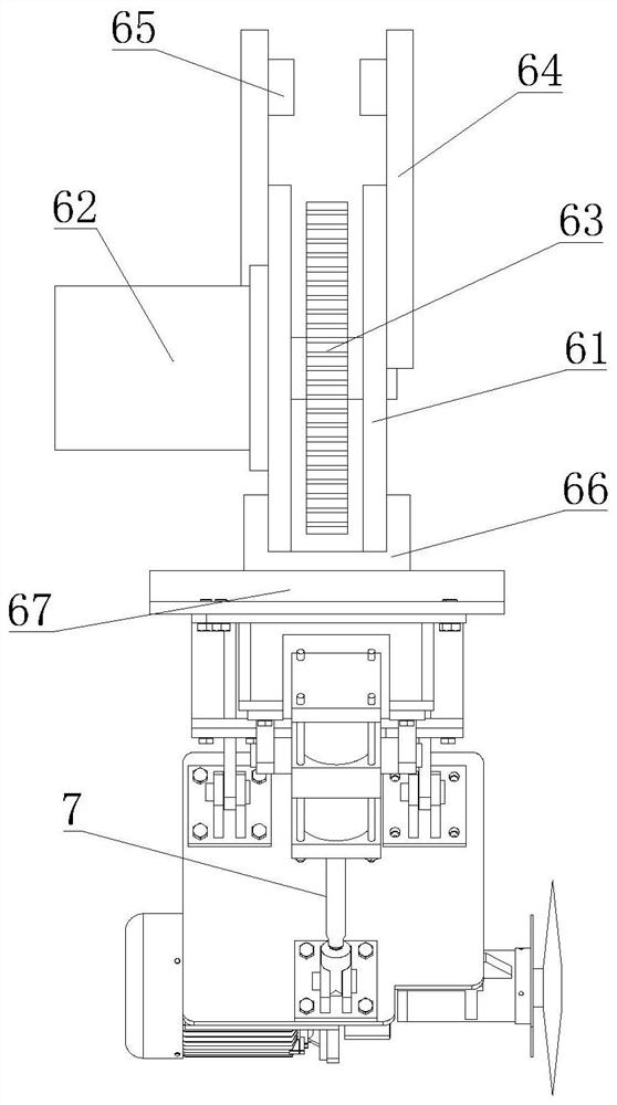
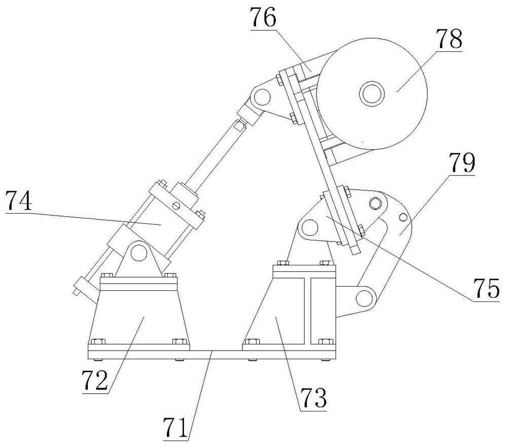
[0035] see Figure 1-7 As shown, an on-site concrete pipe cutting equipment includes a device base 1, a support base 2, a cutting ring 3, a chute 4, a moving component 5, a ring driving component 6, a cutting component 7, an adjusting component 8 and a supporting and fixing component 9 The bottom of the device base 1 is fixedly installed with several groups of moving components 5, and several groups of moving components 5 are linearly and evenly distributed on the bottom of the device base 1, and the support base 2 is fixed...


PUM


Abstract

The invention discloses on-site concrete pipe cutting equipment and a using method thereof. The on-site concrete pipe cutting equipment comprises a device base, a supporting seat, a cutting circular ring, sliding grooves, moving assemblies, an annular driving assembly, a cutting assembly, an adjusting assembly and a supporting fixing assembly; the plurality of moving assemblies are fixedly arranged at the bottom of the device base, and the plurality of moving assemblies are linearly and evenly distributed at the bottom of the device base; the supporting seat is fixedly arranged in the centralposition of the upper end of the device base, the cutting circular ring is fixedly arranged on the supporting seat, and the sliding grooves are formed in the two sides of the cutting circular ring; and the annular driving assembly is slidably connected to the cutting circular ring, the annular driving assembly is connected with the sliding grooves, and the cutting assembly is fixedly arranged at the end, away from the intersection between the annular driving assembly and the cutting circular ring, of the annular driving assembly. The cutting equipment is convenient to move, and a concrete pipedoes not need to be carried, so that the concrete pipe cutting efficiency is improved while the labor intensity is reduced.

Description

technical field [0001] The invention relates to the technical field of concrete pipe cutting, in particular to an on-site concrete pipe cutting equipment. Background technique [0002] Concrete pipes are pipes made of concrete or reinforced concrete for transporting fluids such as water, oil, and gas. Concrete pipes have achieved standardized production in the process of production and processing, but in the process of use, due to the complex geological conditions, the concrete pipe piles of standardized sizes often cannot meet the construction needs, and the concrete pipe piles need to be cut on site to meet the design requirements, but The existing cutting equipment is mainly hand-held, which makes the operator labor-intensive and low-efficiency. However, for larger concrete pipes, the hand-held cutting equipment has low cutting efficiency and poor cutting effect. It is inconvenient to cut in different positions. Contents of the invention [0003] The object of the pre...

Claims


Application Information

Patent Timeline
Patent Type & Authority Applications(China)
IPC IPC(8): B28D1/22B28D1/24B28D7/04
CPCB28D1/227B28D1/24B28D7/04
Inventor 陈仲礼薛英龙潘彪夏秀江刘军李辉平谭长杰佘灿明李贵峙侯江朋
Owner BEIJING URBAN CONSTR DESIGN & DEV GRP CO
Why Eureka
Try Eureka