
Manual stamping device

A technology of stamping device and stamping rod, which is applied in the field of stamping, can solve the problems of operator safety threat and energy waste, and achieve the effects of avoiding direct rigid impact, saving energy and avoiding damage

Pending Publication Date: 2021-03-16
ZHUHAI DAHENGQIN TECH DEV CO LTD
View PDF6 Cites 0 Cited by
  • Summary
  • Abstract
  • Description
  • Claims
  • Application Information

AI Technical Summary

Problems solved by technology

Waste of energy if presses are used
In addition, because these parts are small in size, and the press is electric, it will pose a threat to the safety of the operator during stamping.

Method used


Image

  • Manual stamping device
  • Manual stamping device

Examples


Embodiment Construction

[0022] The technical solutions of the present invention will be clearly and completely described below in conjunction with the accompanying drawings. Apparently, the described embodiments are some of the embodiments of the present invention, but not all of them. Based on the embodiments of the present invention, all other embodiments obtained by persons of ordinary skill in the art without making creative efforts belong to the protection scope of the present invention.

[0023] In the description of the present invention, it should be noted that the terms "center", "upper", "lower", "left", "right", "vertical", "horizontal", "inner", "outer" etc. The indicated orientation or positional relationship is based on the orientation or positional relationship shown in the drawings, and is only for the convenience of describing the present invention and simplifying the description, rather than indicating or implying that the referred device or element must have a specific orientation, ...


PUM


Abstract

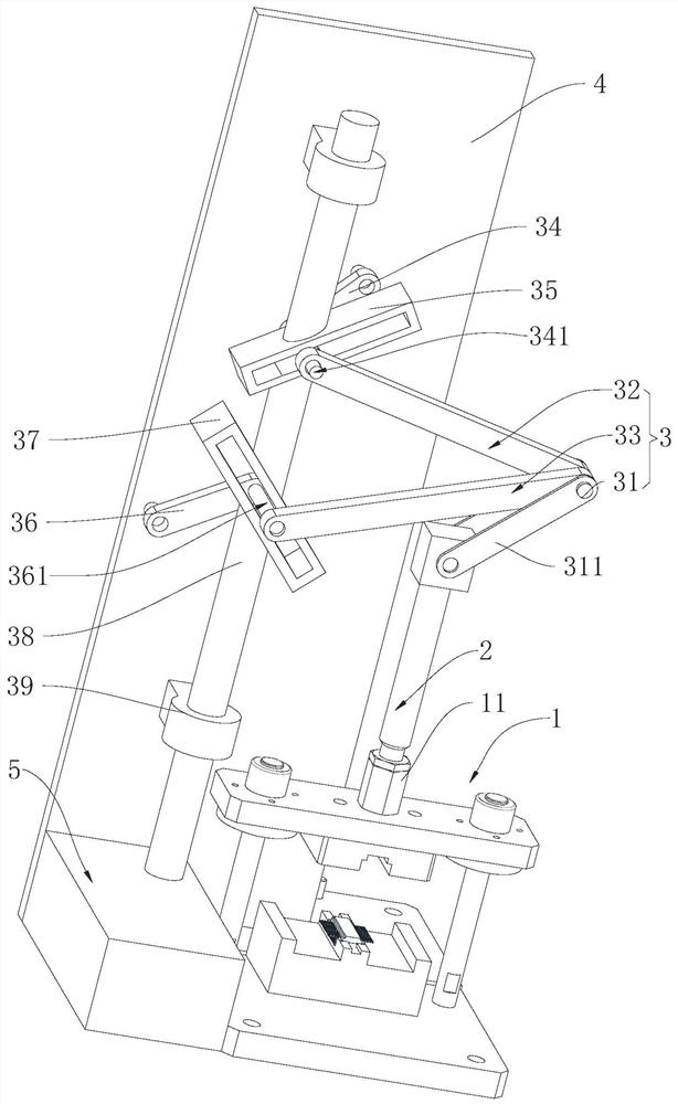
The invention relates to the technical field of stamping, in particular to a manual stamping device. The manual stamping device comprises a supporting base and a stamping rod, wherein a driving assembly for driving the stamping rod to ascend and descend is arranged on one side of the stamping rod, and the driving assembly comprises a main hinge rod, a first auxiliary hinge rod and a second auxiliary hinge rod; one end of the main hinge rod is hinged on the stamping rod, and the first auxiliary hinge rod and the second auxiliary hinge rod are hinged to the other end of the main hinge rod; a first connecting rod is hinged to the other end of the first auxiliary hinge rod, and a second connecting rod is hinged to the other end of the second auxiliary hinge rod; a mounting plate is arranged onone side of the supporting base, and one end of the first connecting rod and one end of the second connecting rod are rotationally connected to the mounting plate; a driving rod is arranged on one side of the mounting plate, and a first driving groove and a second driving groove are formed in the driving rod; the first driving groove drives the first connecting rod to rotate; and the second driving groove drives the second connecting rod to rotate. By driving the driving rod, lifting of the main hinge rod is achieved, and then stamping of the stamping rod is achieved. A motor is not needed, and energy is saved.

Description

technical field [0001] The invention relates to the technical field of stamping, in particular to a manual stamping device. Background technique [0002] Stamping, by means of presses and molds to apply external force to plates, strips, pipes and profiles, etc., to cause plastic deformation or separation, so as to obtain workpieces (stamping parts) of required shape and size. Forming processing method. The mold used for stamping is called stamping die, or punching die for short. Die is a special tool for mass processing materials (metal or non-metal) into required punching parts. Dies are very important in stamping. Without qualified dies, mass stamping production will be difficult; without advanced dies, advanced stamping technology will not be realized. The stamping process, dies, stamping equipment and stamping materials constitute the three elements of stamping processing. Only when they are combined with each other can stamping parts be obtained. [0003] The existin...

Claims


Application Information

Patent Timeline
Patent Type & Authority Applications(China)
IPC IPC(8): B30B1/12B30B15/00
CPCB30B1/12B30B15/00
Inventor 邓练兵余大勇朱俊
Owner ZHUHAI DAHENGQIN TECH DEV CO LTD
Learn More