
Monitoring device for large-scale high-grade numerical control equipment and monitoring method thereof

A monitoring device and high-end technology, applied in the field of CNC equipment maintenance, can solve problems such as dust contamination, monitoring work impact, lack of automation, etc., and achieve the effect of reducing manpower consumption and comprehensive monitoring functions

Inactive Publication Date: 2021-03-16
李佳佳
View PDF0 Cites 0 Cited by
  • Summary
  • Abstract
  • Description
  • Claims
  • Application Information

AI Technical Summary

Problems solved by technology

[0003] 1. When large-scale high-end CNC equipment is running, it is necessary to monitor the running status in real time, so that the staff can keep abreast of the running status of the CNC equipment; due to the certain dust in the workshop environment, after long-term use of the camera used for monitoring, the surface It will be contaminated with dust, which will affect the monitoring work; the existing technology usually relies on manual cleaning, and due to the lack of automatic settings, the consumption of manpower increases;
[0004] 2. When using the camera to monitor the large-scale high-end numerical control equipment in operation in real time, due to the large volume of the numerical control equipment, the position of the camera itself in the prior art is fixed, and it is difficult to meet the comprehensive monitoring functions of multi-angle, multi-height and multi-directional , for this reason, a monitoring device and monitoring method for large-scale high-grade numerical control equipment are proposed

Method used


Image

  • Monitoring device for large-scale high-grade numerical control equipment and monitoring method thereof
  • Monitoring device for large-scale high-grade numerical control equipment and monitoring method thereof
  • Monitoring device for large-scale high-grade numerical control equipment and monitoring method thereof

Examples


Embodiment

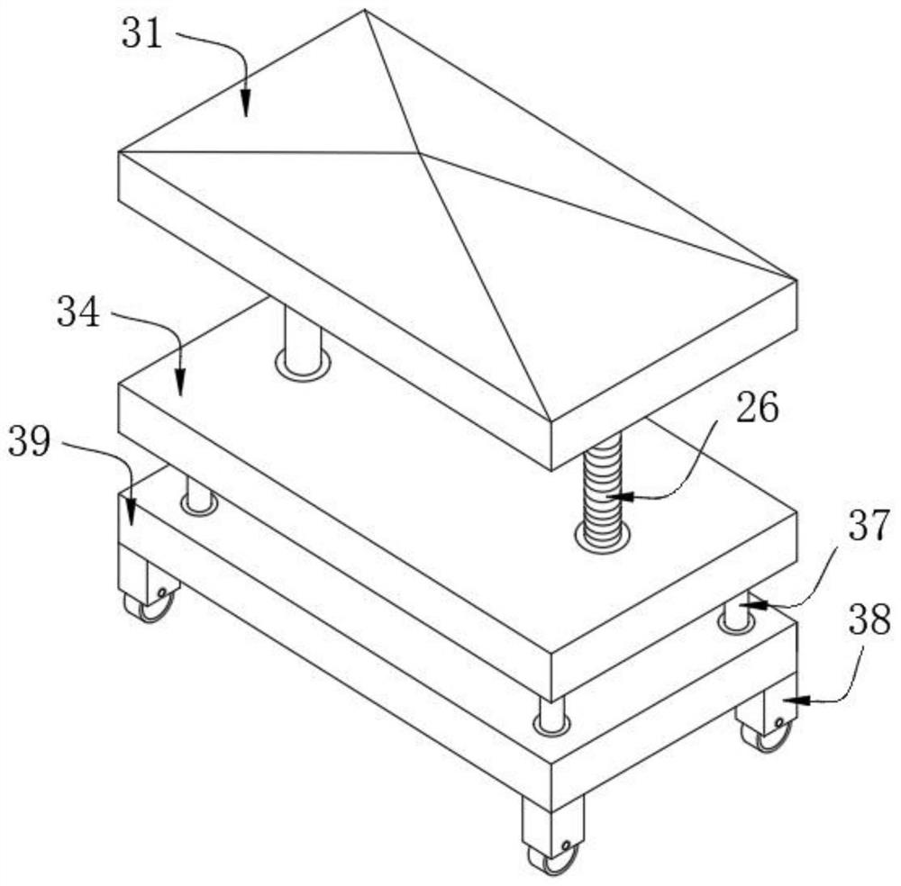
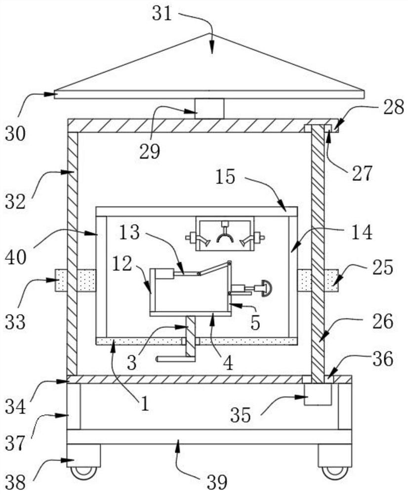
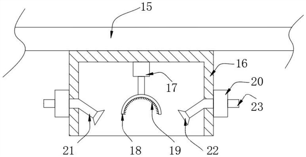
[0030] see Figure 1-5 , The present invention provides a technical solution: a monitoring device for large-scale high-end numerical control equipment, comprising a base plate 1, the interior of the base plate 1 is fixedly connected with a first bearing 2, and the inner ring of the first bearing 2 is fixedly connected with a rotating shaft 3, The top end of the rotating shaft 3 is welded with a baffle plate 4, the top of the baffle plate 4 is riveted with a vertical plate 5, the top of the vertical plate 5 is rotatably connected with an L-shaped plate 6, and one side of the L-shaped plate 6 is welded with a first cylinder 7. A camera 8 is welded to the piston rod of a cylinder 7, an annular plate 9 is threadedly connected to the outer side of the camera 8, a glass cover 10 is fixedly connected to one side of the annular plate 9, and a connecting rod 11 is rotatably connected to the other side of the L-shaped plate 6. The top of the baffle plate 4 is riveted with a support plat...


PUM


Abstract

The invention relates to a monitoring device for large-scale high-grade numerical control equipment and monitoring method thereof. The monitoring device comprises a bottom plate, a first bearing is fixedly connected to the inside of the bottom plate, a rotating shaft is fixedly connected to the inner ring of the first bearing, a baffle is welded to one end of the top of the rotating shaft, and a vertical plate is riveted to the top of the baffle; an L-shaped plate is rotatably connected to the top of the vertical plate, a first air cylinder is welded to one side of the L-shaped plate, a camerais welded to a piston rod of the first air cylinder, an annular plate is connected to the outer side of the camera in a threaded mode, and a glass cover is fixedly connected to one side of the annular plate. According to the monitoring device for the large-scale high-grade numerical control equipment and the monitoring method thereof, a connecting rod is arranged between a second air cylinder andthe L-shaped plate, the second air cylinder can drive an L-shaped plate to vertically steer by 90 degrees through the connecting rod, so that the first air cylinder can drive the camera to enter a box body, and a brush and an air pump can uniformly clean dust on the glass cover outside the camera; and through automatic arrangement, the manpower consumption is reduced.

Description

technical field [0001] The invention relates to the technical field of numerical control equipment maintenance, in particular to a monitoring device and a monitoring method for large-scale high-end numerical control equipment. Background technique [0002] The existing numerical control equipment refers to the equipment that applies this technology. The numerical control technology is also called the computer numerical control technology. At present, it is the technology that uses the computer to realize the digital program control. This technology uses the computer to execute the sequential logic control function of the movement track of the equipment and the operation of the peripherals according to the control program stored in advance. Because the computer is used to replace the numerical control device originally composed of hardware logic circuits, the realization of various control functions such as storage, processing, operation, and logical judgment of input operati...

Claims


Application Information

Patent Timeline
Patent Type & Authority Applications(China)
IPC IPC(8): F16M11/18F16M11/42B08B1/04B08B5/02H04N7/18H04N5/225
CPCF16M11/18F16M11/42B08B5/02H04N7/18H04N23/00H04N23/695B08B1/32B08B1/12
Inventor 李佳佳
Owner 李佳佳
Learn More