Locking mechanism of integrated cooker module

An integrated cooker and locking technology, which is applied in the field of integrated cookers, can solve the problems that there is no integrated cooker module installation and mechanical locking mechanism, it is not universally applicable, time-consuming and labor-intensive, etc., to save energy, facilitate maintenance, disassembly, and operation simple and fast effect

Active Publication Date: 2021-03-16
嵊州市浙江工业大学创新研究院
View PDF10 Cites 0 Cited by
  • Summary
  • Abstract
  • Description
  • Claims
  • Application Information

AI Technical Summary

Problems solved by technology

With the upgrading of consumption, traditional kitchen appliances have begun to develop into new integrated kitchen appliances. The new integrated kitchen appliances have a broader market because of their integrated modular design; The modularization of the stove is one of them, but the current modularization of the integrated stove still uses the traditional installation methods of bolts and screws to connect the module body to the main body of the integrated stove. Although the modularization reduces the use of bolts and screws, this way The installation method is still time-consuming and labor-intensive, and it is cumbersome to disassemble when repairing the main body of the module
[0003]The existing method of modular installation of integrated stoves is proposed, and the minimal use of bolts and screws is used for fastening, and the main body of the module is fixed and locked through a complex electrical control structure. , but this method can only be used when the power is on, and it is not universally applicable
There is no installation and mechanical locking mechanism of this integrated stove module at present

Method used


Image

  • Locking mechanism of integrated cooker module
  • Locking mechanism of integrated cooker module
  • Locking mechanism of integrated cooker module

Examples


Embodiment Construction

[0026] In order to make the object, technical solution and advantages of the present invention clearer, the present invention will be further described in detail below in conjunction with the accompanying drawings and embodiments. It should be understood that the specific embodiments described here are only used to explain the present invention, not to limit the present invention.

[0027] On the contrary, the invention covers any alternatives, modifications, equivalent methods and schemes within the spirit and scope of the invention as defined by the claims. Further, in order to make the public have a better understanding of the present invention, some specific details are described in detail in the detailed description of the present invention below. The present invention can be fully understood by those skilled in the art without the description of these detailed parts.

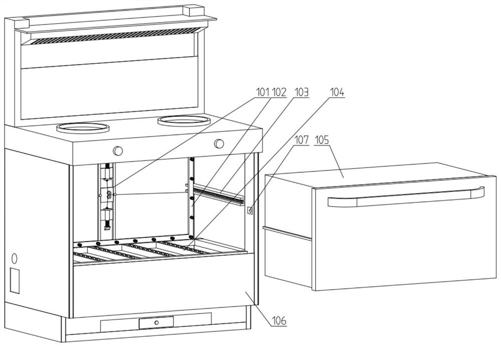
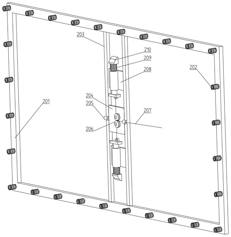
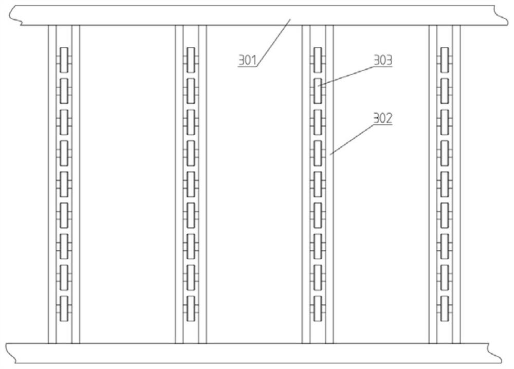
[0028] like Figure 1-10 As shown, a locking mechanism of an integrated stove module includes an inte...


PUM


Abstract

The invention discloses a locking mechanism of an integrated cooker module, and belongs to the technical field of integrated cookers. The integrated cooker comprises an integrated cooker body, whereina containing space is formed in the integrated cooker body, and a module body is installed in the containing space in a matched mode. The locking mechanism is characterized in that a rear frame partis installed on the rear end face of the containing space, side limiting grooves are formed in the two side faces of the containing space, a bottom supporting mechanism is installed at the bottom of the containing space, the front end of the containing space is an open end, a mechanical locking mechanism is installed on the rear frame part, side protrusions matched with the side limiting grooves are installed on the side faces of the module body, and a clamping assembly matched with the mechanical locking mechanism is installed on the rear end face. By arranging the bottom supporting mechanism, the side limiting grooves, the rear frame part and the mechanical locking mechanism, a traditional connection mode is avoided, the influence of inexistance or existance of electricity is avoided, and mounting and dismounting can be achieved only by simply pushing and pulling the module body; and the operation is convenient and fast, physical strength is saved, and meanwhile the installation efficiency of installation personnel is improved.

Description

technical field [0001] The invention belongs to the technical field of integrated stoves, and in particular relates to a locking mechanism of an integrated stove module. Background technique [0002] The integrated stove is a collection of various functions such as range hood, stove, disinfection cabinet, steam box, etc. It has the characteristics of high oil fume absorption rate, energy saving and environmental protection, and more efficient function combination. With the upgrading of consumption, traditional kitchen appliances have begun to develop into new integrated kitchen appliances. The new integrated kitchen appliances have a broader market because of their integrated modular design; The modularization of the stove is one of them, but the current modularization of the integrated stove still uses the traditional installation methods of bolts and screws to connect the module body to the main body of the integrated stove. Although the modularization reduces the use of b...

Claims


Application Information

Patent Timeline
IPC IPC(8): F24C3/00F24C15/08F24C15/12F24C15/18
CPCF24C3/00F24C15/08F24C15/12F24C15/18
Inventor 丁振宇郭礼建欧玉洁宋家辉殷佳豪周水清唐帅
Owner 嵊州市浙江工业大学创新研究院
Why Eureka
Try Eureka