
Method, system, storage medium and electronic equipment for seamless realization of LED splicing wall system

A realization method and splicing wall technology, applied in the direction of transmission system, digital output to display equipment, electrical components, etc., can solve problems such as network congestion, large data distribution of switches, and failure of nodes to receive notification messages

Active Publication Date: 2022-06-21
GUANGDONG VTRON TECH CO LTD
View PDF0 Cites 0 Cited by
  • Summary
  • Abstract
  • Description
  • Claims
  • Application Information

AI Technical Summary

Problems solved by technology

[0002] At present, ultra-large-scale LED splicing walls are widely used in the market. LED splicing display systems are used in military, banking, electric power and other industries, and in some special industries such as the military, very high requirements are placed on the redundant functions of LED splicing display systems. At the same time When the system is very large, the data distribution volume of the switch is also very large, especially the distribution of a large number of real-time heartbeats is more likely to cause network congestion, and the large data distribution is likely to cause some nodes to fail to receive notification messages when the system performs redundant switching. Redundant switching, when there is a problem with some active and standby single or few image output transmitter nodes in the super large LED system, the current LED hardware cannot achieve seamless real-time response for redundant switching, and manual intervention is required for signal switching

Method used


Image

  • Method, system, storage medium and electronic equipment for seamless realization of LED splicing wall system
  • Method, system, storage medium and electronic equipment for seamless realization of LED splicing wall system

Examples


Embodiment 1

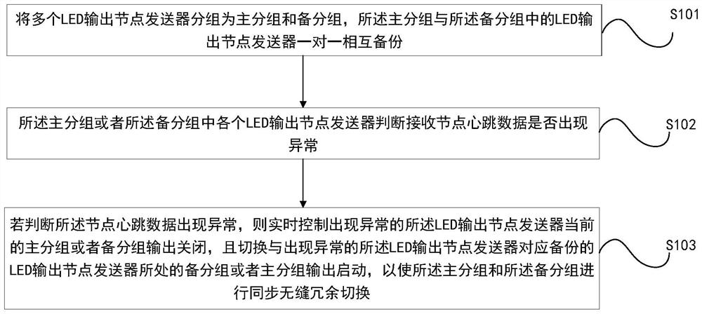
[0042] like figure 1 As shown, it is a schematic flowchart of a seamless implementation method of an LED video wall system according to an embodiment of the present invention, and the method includes the steps:

[0043] S101. Group multiple LED output node transmitters into a primary group and a backup group, and the primary group and the LED output node transmitters in the backup group back up one-to-one with each other;

[0044] This method can realize seamless redundant switching of the entire LED splicing wall system when the main and standby redundant LED output node transmitters fail when the super-large network data distribution amount is large. In step S101, a pure software control method is adopted. Controlling the LED output node transmitter includes adjusting the brightness and color temperature of the LED output node transmitter, enabling control of the LED output node transmitter output, and controlling the LED output node transmitter output to turn on or off. Thi...

Embodiment 2

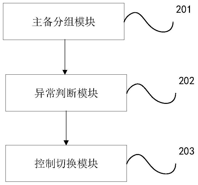
[0061] like figure 2 Shown is a seamless implementation system of an LED splicing wall system according to an embodiment of the present invention, including:

[0062] The main and backup grouping module 201 is used for grouping a plurality of LED output node transmitters into a main group and a backup group, and the main group and the LED output node transmitters in the backup group back up one-to-one with each other;

[0063] This system can realize seamless redundant switching of the entire LED splicing wall system when the main and standby redundant LED output node transmitters fail when the super-large network data distribution volume is large. The transmitter controls, including the adjustment of the brightness and color temperature of the LED output node transmitter, as well as the enabling control of the LED output node transmitter output, and controlling the LED output node transmitter output to turn on or off. Pure software is used in this method. In the control mod...


PUM


Abstract

The present invention relates to a method, system, readable medium and electronic equipment for seamless realization of LED splicing wall system. The LED output node transmitters in the standby group back up one-to-one; each LED output node transmitter in the main group or the standby group judges whether the heartbeat data of the receiving node is abnormal; if it is judged that the heartbeat data of the node occurs Abnormal, real-time control of the main group or backup group where the abnormal LED output node transmitter is located is closed, and switch the backup group where the LED output node transmitter corresponding to the abnormal LED output node transmitter is located Or the output of the main group is started, so that the main group and the standby group perform synchronous seamless redundancy switching. The invention is used to realize the real-time seamless main-standby redundancy of the ultra-large LED splicing wall system, and does not require personnel intervention or additional costs such as hardware.

Description

technical field [0001] The invention relates to the technical field of LED splicing display, and more particularly, to a seamless realization method, system, storage medium and electronic device of an LED splicing wall system. Background technique [0002] At present, ultra-large-scale LED splicing walls are widely used in the market, and LED splicing display systems are used in the military, banking, electric power and other industries, and in some special industries such as the military, very high requirements are placed on the redundant functions of the LED splicing display system. When the system is very large, the data distribution volume of the switch is also very large, especially the continuous distribution of a large number of real-time heartbeats is more likely to cause network congestion, and the large data distribution is likely to cause some nodes to fail to receive notification messages when the system performs redundant switching. Redundant switching. When the...

Claims


Application Information

Patent Timeline
Patent Type & Authority Patents(China)
IPC IPC(8): G06F3/14H04L41/0663
CPCG06F3/1446G06F3/1454H04L41/0663
Inventor 刘雄伟
Owner GUANGDONG VTRON TECH CO LTD
Learn More