Arc extinguishing chamber and arc extinguishing device
An arc-extinguishing device and arc-extinguishing chamber technology, applied in electrical components, electrical switches, circuits, etc., can solve the problems of unsatisfactory arc-extinguishing effect of the arc-extinguishing device, improve the short-circuit breaking capacity, ensure the arc-extinguishing speed, and reduce the volume. Effect
- Summary
- Abstract
- Description
- Claims
- Application Information
AI Technical Summary
Problems solved by technology
Method used
Image

Examples
Embodiment 1
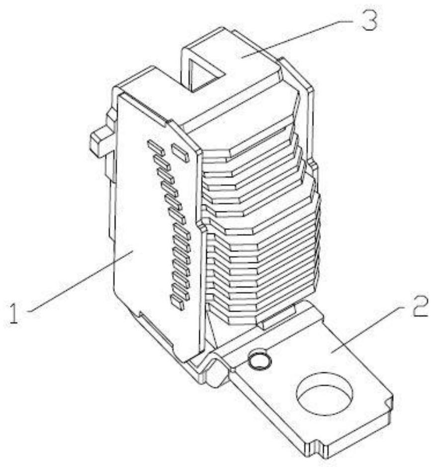
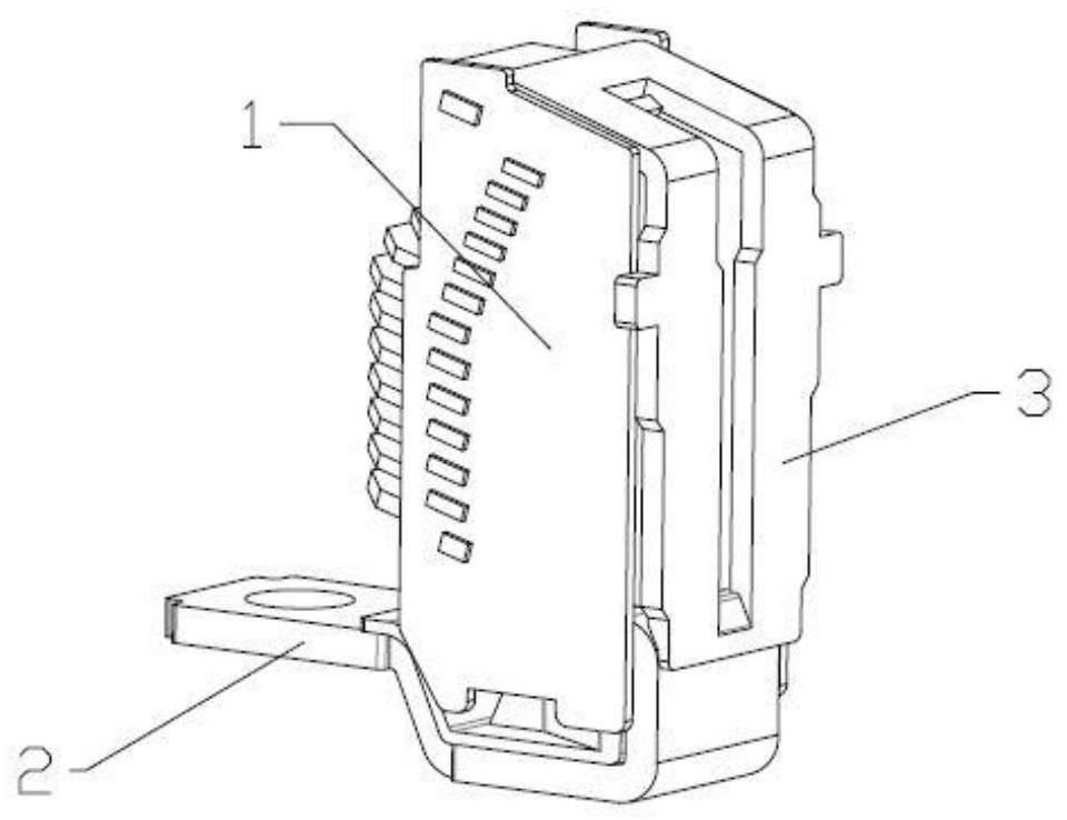
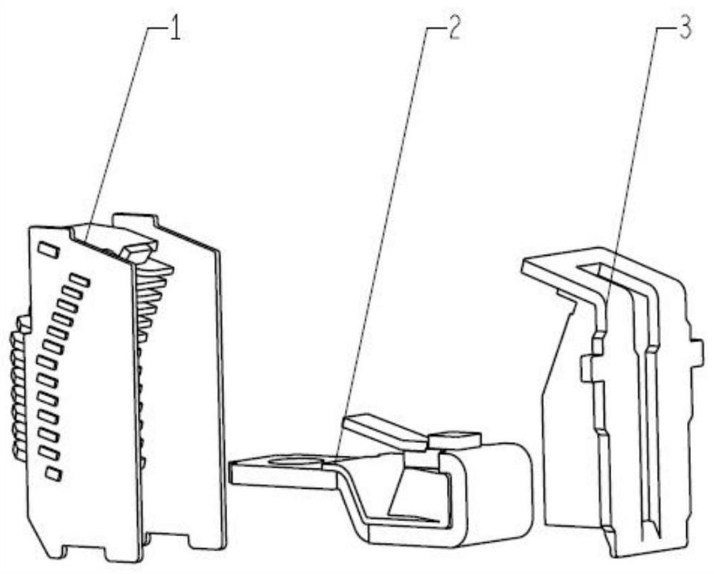
[0036] Embodiment 1 This embodiment provides an arc extinguishing chamber 1, which includes a plurality of arc extinguishing grids, and oppositely arranged arc baffles 101 1 and 101 2, arc baffle 101 1 and arc baffle 101 2 Installing slots corresponding to the number of arc extinguishing grid pieces are opened on the vertically opposite inner sidewalls. As mentioned above, in this embodiment, the arc extinguishing grids are arranged in the chamber between the arc chute 101 and the arc chute 101 2 in parallel and at intervals along the vertical direction, and the arc extinguishing grids have a herringbone guide The arc grooves, the herringbone arc striking grooves of the two adjacent arc extinguishing grids are arranged alternately - this technical point is reflected in the existing patents, and it is not the gist of this embodiment, so it will not be described again.
[0037] Based on the above, among the above-mentioned arc extinguishing grids arranged vertically and horizont...
Embodiment 2
[0045] Embodiment 2 The difference between this embodiment and Embodiment 1 is that in this embodiment, the thickness of the upper grid sheet 103 in the upper grid sheet group gradually increases from top to bottom, and the increase range is kept within 0.01~0.1mm The thickness of the lower grid sheet 104 in the lower grid sheet group is 0.2mm more than the thickness of the upper grid sheet 103, and the lower grid sheet 104 and the upper grid sheet 103 are distinguished from the thickness level to realize the upper grid sheet group and the lower grid sheet. There is a large gap in the length of the arc cut by the grid sheet group, so as to achieve the purpose of improving the arc extinguishing effect.
[0046] As for the gap between the grids, it can be consistent with the gap setting in Embodiment 1; or, in another embodiment, the gap width between the upper grids 103 in the upper grid group gradually increases from top to bottom .
[0047] In addition, the thickness of the ...
Embodiment 3
[0049] Embodiment 3 Based on the above embodiments, in order to improve the arc striking effect of the arc extinguishing chamber 1 and further improve the arc extinguishing efficiency of the arc extinguishing chamber 1, an upper arc striking sheet is arranged above the upper grid sheet group in this embodiment 102. The upper arc runner 102 is finally arranged parallel to and spaced apart from the upper grid group, and the gap between it and the upper grid group is preferably larger than the gap between each arc-extinguishing grid in the upper grid group. Such as Figure 6 As shown, in a specific implementation structure, it can be consistent with the gap in the lower grid group.
[0050] In the above embodiment, in order to improve the sealing performance of the arc extinguishing chamber 1, the arc extinguishing grid at the bottom layer—that is, Figure 6 The bottom grid piece 105 shown in the figure is riveted and fixed with the arc shield 101 .
PUM
 Abstract
Description
Claims
Application Information
 - R&D
- Intellectual Property
- Life Sciences
- Materials
- Tech Scout
- Unparalleled Data Quality
- Higher Quality Content
- 60% Fewer Hallucinations
Browse by: Latest US Patents, China's latest patents, Technical Efficacy Thesaurus, Application Domain, Technology Topic, Popular Technical Reports.
© 2025 PatSnap. All rights reserved.Legal|Privacy policy|Modern Slavery Act Transparency Statement|Sitemap|About US| Contact US: help@patsnap.com