UPS power supply control method and device, and terminal equipment

A technology of power supply control and power supply mode, applied in the direction of circuit devices, electrical components, emergency power supply arrangement, etc., can solve problems such as UPS working failure, influence of three-phase mains rectification and voltage stabilization circuit, and reduce UPS reliability, so as to improve reliability sexual effect

Pending Publication Date: 2021-03-16
ZHANGZHOU KEHUA ELECTRIC TECH CO LTD
View PDF7 Cites 2 Cited by
  • Summary
  • Abstract
  • Description
  • Claims
  • Application Information

AI Technical Summary

Problems solved by technology

[0005] In view of this, the embodiment of the present invention provides a UPS power supply control method, device and terminal equipment to solve the problem that in the prior art, when the output three-phase load is an unbalanced load, the DC bus may generate a large inrush current, which is harmful to the The three-phase mains rectification and voltage stabilization circuit has an impact, and may even damage the components of the three-phase mains rectification circuit, causing UPS malfunctions and reducing the reliability of the UPS.

Method used


Image

  • UPS power supply control method and device, and terminal equipment
  • UPS power supply control method and device, and terminal equipment
  • UPS power supply control method and device, and terminal equipment

Examples


Embodiment Construction

[0022] In the following description, specific details such as specific system structures and technologies are presented for the purpose of illustration rather than limitation, so as to thoroughly understand the embodiments of the present invention. It will be apparent, however, to one skilled in the art that the invention may be practiced in other embodiments without these specific details. In other instances, detailed descriptions of well-known systems, devices, circuits, and methods are omitted so as not to obscure the description of the present invention with unnecessary detail.

[0023] In order to illustrate the technical solutions of the present invention, specific examples are used below to illustrate.

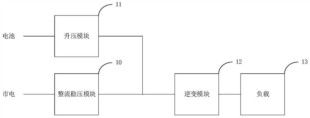
[0024] see figure 1 , which shows the structure of a UPS power supply system provided by an embodiment of the present invention, including a rectifying and stabilizing module 10 , a boosting module 11 , an inverter module 12 and a load 13 .

[0025] The UPS power supp...


PUM


Abstract

The invention belongs to the technical field of power electronics, and provides a UPS power supply control method and device, and terminal equipment. The method comprises the following steps: acquiring the commercial power input voltage of a UPS; acquiring the state of an output load of the UPS; and if the commercial power input voltage of the UPS and the state of the output load of the UPS meet afirst preset condition, switching the power supply mode of the UPS from mains power supply to battery power supply, wherein the first preset condition is that the commercial power input voltage of the UPS is higher than a first preset voltage threshold and the state of the output load of the UPS is an unbalanced load; and when the power supply mode of the UPS is battery power supply, the difference between the peak value of the voltage output by a battery and the trough value of the ripple voltage of a DC bus of the UPS is smaller than a preset difference. According to the invention, the reliability of UPS power supply can be improved.

Description

technical field [0001] The invention belongs to the technical field of power electronics, and in particular relates to a UPS power supply control method, device and terminal equipment. Background technique [0002] Uninterruptible Power Supply (UPS) is an uninterruptible power supply with an energy storage device. It is mainly used to provide uninterruptible power to equipment that requires high power stability and is widely used. [0003] In the prior art, when the mains input is normal, the UPS rectifies and stabilizes the three-phase mains, and supplies the output three-phase load through the inverter; when the mains is interrupted, the energy storage device in the UPS, that is, the battery, passes through the booster circuit Output DC voltage, and then supply power to the three-phase output load through the inverter. [0004] However, when the output three-phase load is an unbalanced load, the DC bus may generate a large inrush current, which will affect the three-phase...

Claims


Application Information

Patent Timeline
Patent Type & Authority Applications(China)
IPC IPC(8): H02J9/06
CPCH02J9/062
Inventor 张堡森王定富卢雄伟郑延敏徐敏
Owner ZHANGZHOU KEHUA ELECTRIC TECH CO LTD
Why Eureka
Try Eureka